

Industrial wireless remote control B system receiver mainboard test tool
An industrial wireless and testing tooling technology, which is applied in receiver monitoring, electronic circuit testing, signal transmission systems, etc., can solve the problems of unable to test the main board by pressing and fixing it, and it is difficult to fix multiple test main boards at the same time, so as to prevent missed detection and false detection Check and improve the effect of efficiency
Patent Information
- Authority / Receiving Office
- CN · China
- Current Assignee / Owner
- Publication Date
- 2020-12-29
Smart Images
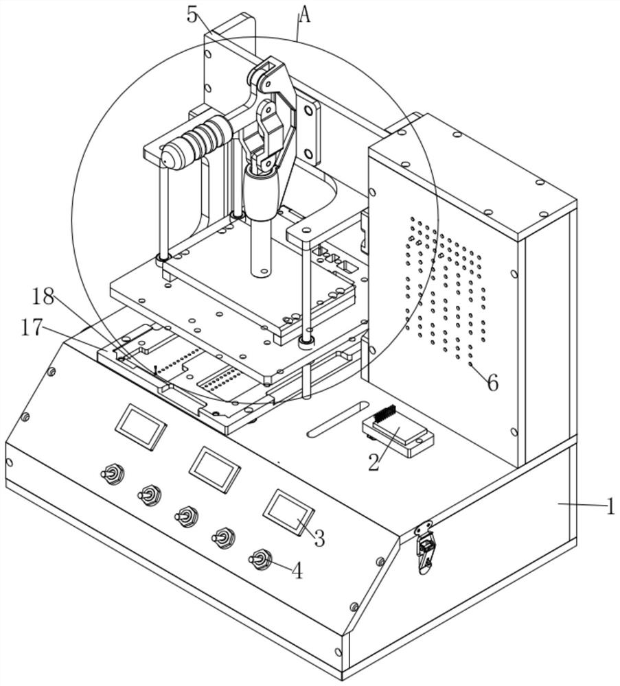
Figure 1 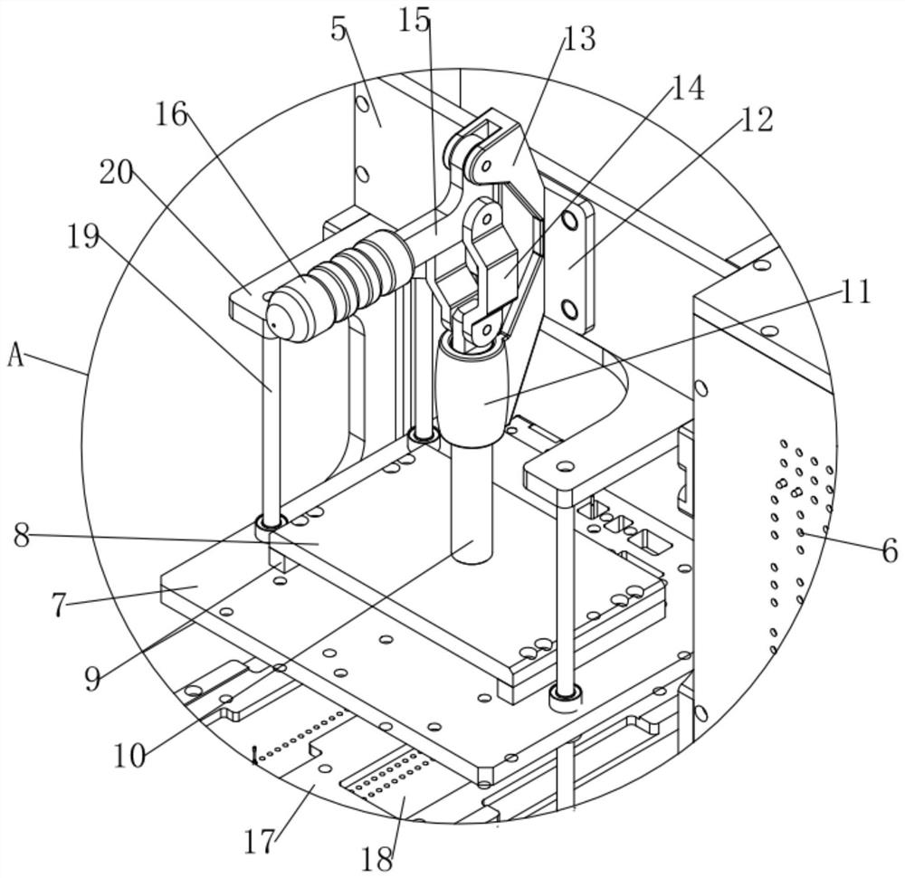
Figure 2 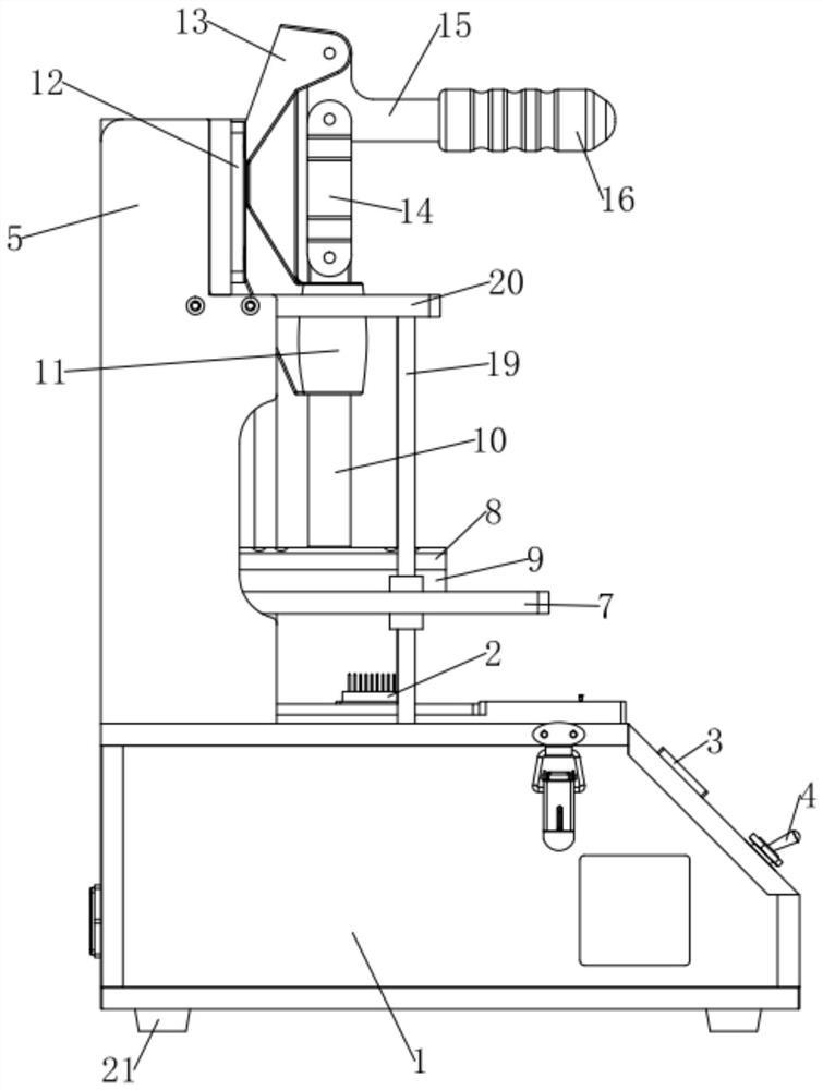
Figure 3
Abstract
Description
technical field
[0001] The invention relates to the technical field of industrial wireless remote control test equipment, and more specifically relates to an industrial wireless remote control B system receiver motherboard test tooling. Background technique
[0002] Wireless remote control refers to the realization of non-contact remote control of the controlled object, and is widely used in the fields of industrial control, aerospace, and home appliances. Wireless remote control and wireless transmission systems increase freedom of movement compared to wired and infrared devices. As a result, wireless remote control devices and wireless transmission systems are increasingly used in industrial fields. Compared with the cable connection, the advantage is that the installation cost is low (no wiring, no underground engineering, no cable trough), improved flexibility and reduced maintenance costs. Wireless remote control technology has been widely used in life, often used in v...
Examples
Embodiment
[0029] see figure 1 , a kind of industrial wireless remote control B system receiver mainboard test tooling, comprising a test machine 1, the upper end of the test machine 1 is fixedly connected with a support plate 5, the front end of the support plate 5 is fixedly connected with a first fixed plate 12, the first fixed The front end of the plate 12 is fixedly connected with a triangular connection block 13 and a casing 11, and a sliding rod 10 is movably inserted in the casing 11, and the upper part of the left and right ends of the sliding rod 10 is movably hinged with a rotating plate 14 through the first hinge shaft. The upper part of one end close to the rotating plate 14 is hinged with a triangular handle 15 through the second hinge shaft. Plate 8, two fixed blocks 9 are fixedly connected to the lower end of the clamp fixture 2, the lower ends of the two fixed blocks 9 are fixedly connected to the pressing plate 7, and the front end of the support plate 5 is fixedly conn...