
Automatic steel rail shifting and feeding mechanism and method
A rail and automatic technology, applied in the direction of conveyor objects, transportation and packaging, etc., can solve the problems of mutual contact, labor and labor
Patent Information
- Authority / Receiving Office
- CN · China
- Patent Type
- Applications(China)
- Current Assignee / Owner
- Publication Date
- 2021-03-26
Smart Images
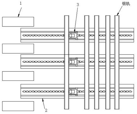
Figure 1 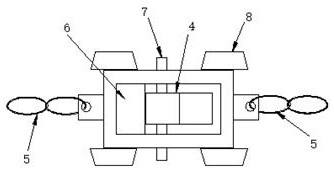
Figure 2 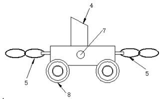
Figure 3
Abstract
Description
technical field
[0001] The invention belongs to the technical field of rail transportation for operation transportation, and in particular relates to an automatic distribution and feeding mechanism for rails and a method thereof. Background technique
[0002] During the production and manufacture of turnout rails, in order to facilitate the operation of workers and improve production efficiency, the processing machine tools will be equipped with special rail loading platforms. Rail loading platform (see figure 1 ) is mainly composed of a working roller table 1, a multi-group material rack 2 and a rail distribution feeding mechanism 3. Wherein, the rack 2 is mainly used to bear the weight of the rail. The rail distribution and feeding mechanism 3 is a chain transmission mechanism with a push block 4: (such as figure 2 , image 3 Shown) rail distribution feeding mechanism 3 is made up of push block 4, chain 5, block 6, bearing pin 7, roller 8. It is used to control the s...
Examples
Embodiment Construction
[0038] Attached below Figure 5-13 Specific examples of the present invention are described.
[0039] The following examples facilitate a better understanding of the present invention, but do not limit the present invention. The following embodiments are only some of the embodiments of the present invention, but not all of them. The components and materials used in the following examples are commercially available unless otherwise specified.
[0040] In the present invention, unless otherwise clearly specified and limited, in the absence of a contrary statement, "upper, lower, left, right, inner, outer, top, bottom, vertical, horizontal" etc. are included in the terms The orientation words only represent the orientation of the term in the normal use state, or for the convenience of describing the present invention and simplifying the description, or the common name understood by those skilled in the art, unless otherwise clearly specified and limited, it should not be regard...