

Dual-motor hybrid power drive system for rear drive
A technology of hybrid power and drive system, which is applied to the layout of multiple prime movers, power devices, and air pressure power devices of general power devices, and can solve the problems of limited fuel saving rate, large pollutant discharge, and fuel saving effect. no problem
Patent Information
- Authority / Receiving Office
- CN · China
- Patent Type
- Applications(China)
- Current Assignee / Owner
- Publication Date
- 2021-06-08
- Estimated Expiration
- Not applicable · inactive patent
Smart Images
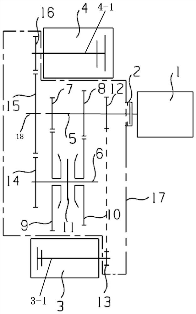
Figure 1 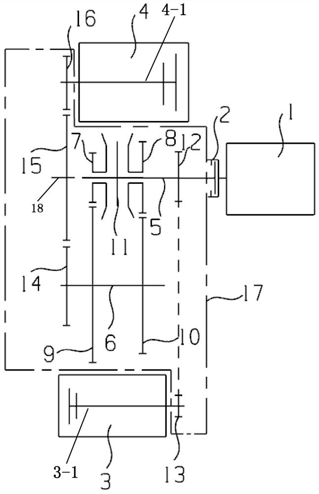
Figure 2
Abstract
Description
technical field
[0001] The invention relates to the technical field of automobile power transmission, in particular to a dual-motor hybrid drive system for rear drive. Background technique
[0002] With the continuous consumption of non-renewable energy, the lack of energy and the national restrictions on vehicle exhaust emissions have seriously restricted the development of traditional fuel vehicles. There are also clear requirements for the fuel consumption of commercial vehicles. At present, most of the rear-drive longitudinal hybrid transmission technical solutions adopt the planetary series-parallel solution or the single-gear series-parallel technical solution, but the fuel-saving rate of these two solutions is very limited, and the fuel-saving effect is not good. , the pollutant emissions are still relatively large. SUMMARY OF THE INVENTION
[0003] The purpose of the present invention is to aim at the deficiencies of the prior art, and to provide a dual-motor hyb...
Examples
Embodiment 1
[0017] Example 1, as figure 1 As shown, when a synchronizer 11 is arranged between the first-speed driven gear 9 and the second-speed driven gear 10, the synchronizer 11 is circumferentially fixed on the intermediate shaft 6, the first-speed driving gear 7, the second-speed driving gear 8 are circumferentially fixed on the input shaft 5, the first-speed driven gear 9 and the second-speed driven gear 10 are clearance-fitted on the intermediate shaft 6, and the first-speed driven gear 9 and the second-speed driven gear 10 face each other. One end is respectively provided with engaging teeth, and the ring gear of the synchronizer 11 corresponds to the engaging teeth of the first-speed driven gear 9 and the second-speed driven gear 10 respectively, so that the synchronizer 11 is connected to the corresponding first-speed driven gear 9 or second-speed The driven gear 10 is engaged to complete the power transmission between the input shaft 5 and the intermediate shaft 6, and realize...
Embodiment 2
[0018] Example 2, as figure 2As shown, when a synchronizer 11 is arranged between the first-speed driving gear 7 and the second-speed driving gear 8, the synchronizer 11 is circumferentially fixed on the input shaft 5, and the first-speed driving gear 7 and the second-speed driving gear 8 are respectively The first-speed driven gear 9 and the second-speed driven gear 10 are respectively fixed on the intermediate shaft 6 in the circumferential direction, and the first-speed driving gear 7 and the second-speed driving gear 8 are respectively arranged at the opposite ends. Engagement teeth, the ring gear of the synchronizer 11 corresponds to the engaging teeth of the first-speed driving gear 7 and the second-speed driving gear 8 respectively, so that the synchronizer 11 is engaged with the corresponding first-speed driving gear 7 or the second-speed driving gear 8, and the completion is completed. The power transmission between the input shaft 5 and the intermediate shaft 6 real...