
Mosquito-borne intelligent detection terminal equipment
A technology for detecting terminals and equipment, which is applied in the fields of resisting vector-borne diseases, fumigators, televisions, etc., and can solve problems such as inability to capture and observe mosquitoes
Patent Information
- Authority / Receiving Office
- CN · China
- Patent Type
- Applications(China)
- Current Assignee / Owner
- Publication Date
- 2021-09-10
Smart Images
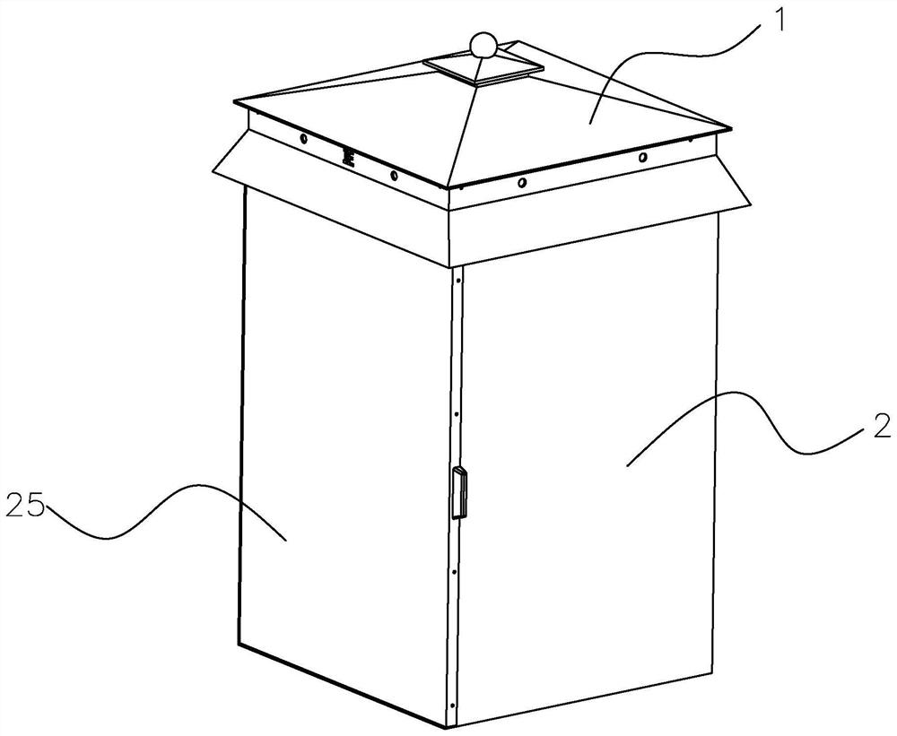
Figure 1 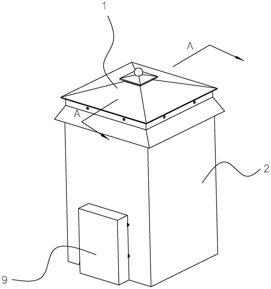
Figure 2 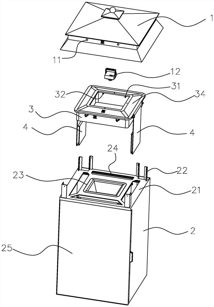
Figure 3
Abstract
Description
technical field
[0001] The invention relates to the technical field of mosquito capture equipment, in particular to an intelligent detection terminal equipment for mosquito vectors. Background technique
[0002] With the development of science, human beings continue to explore the natural field. Since insects such as mosquitoes are closely related to human life, and mosquitoes are also one of the main ways for the transmission of infectious diseases, relevant scientific research institutions usually target specific mosquitoes in a certain experimental area. Capture, and then analyze the number of mosquitoes sampled to infer the proportion of specific mosquitoes in the experimental area or even in the area, and then carry out next-step disinfecting or other processing on the mosquitoes based on the statistical data.
[0003] The invention patent with the Chinese patent application number 201810402149.0 discloses an insect trap. The trap includes: a trap shell, the trap shell h...
Examples
Embodiment Construction
[0035] The present invention will be further described in conjunction with the accompanying drawings and specific embodiments.
[0036] refer to Figure 1 to Figure 9, the present embodiment 1 proposes a mosquito vector intelligent detection terminal device, including a box body 2, a box body cover 1 that is set on the box body 2, and multiple A first through hole 11, a second camera 12 is arranged at the center of the lower surface of the box cover 1, a liquid evaporation box 3 is arranged under the inner surface of the box cover 1, and the liquid evaporation box 3 is movable An upper cover 34 is provided, and the liquid evaporating box 3 is a hollow annular structure, and the first flow guide hole 31 and the second flow guide hole 32 are arranged on the liquid evaporating box 3, and the circumference measurement of the liquid evaporating box 3 A plurality of second through holes 33 are evenly arranged on the surface, and two heating chips 4 are plugged into the liquid evapo...