
Polylactic acid devolatilization device with built-in uniform distributor
A technology of a devolatilization device and a homogenizer, which is applied in the field of polylactic acid, and can solve problems such as the inability to shorten the diffusion distance of the liquid film, reduce the devolatilization efficiency, and high energy consumption
Patent Information
- Authority / Receiving Office
- CN · China
- Current Assignee / Owner
- Publication Date
- 2021-09-10
- Estimated Expiration
- Not applicable · inactive patent
Smart Images
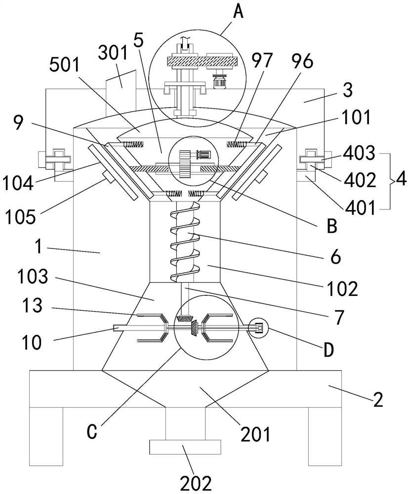
Figure 1 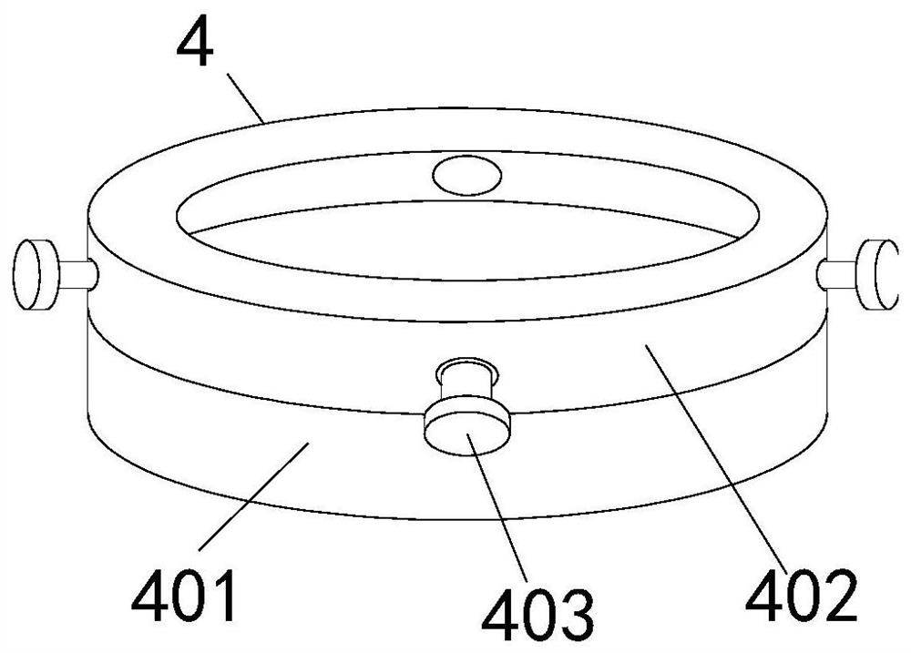
Figure 2 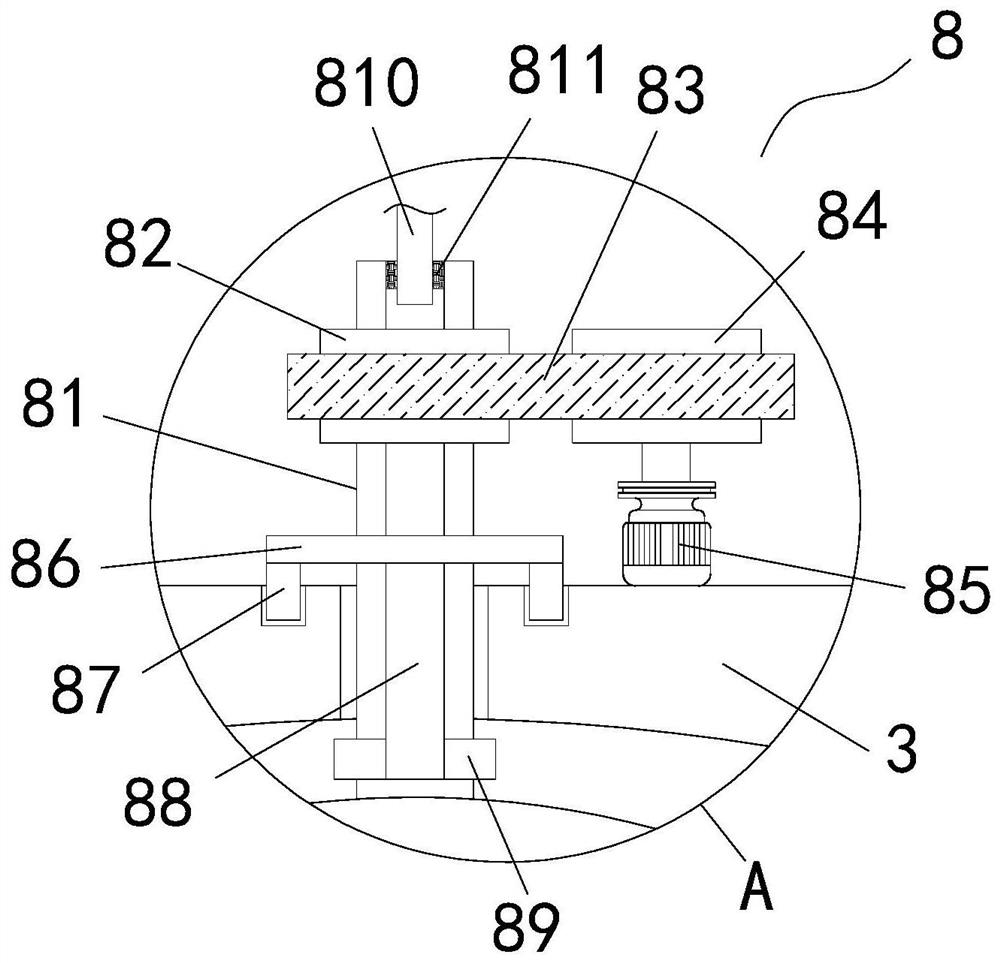
Figure 3
Abstract
Description
technical field
[0001] The invention relates to the technical field of polylactic acid, in particular to a polylactic acid devolatilization device with a built-in uniform distributor. Background technique
[0002] At present, the two major problems of environmental pollution and resource shortage have posed a major threat to human society. It is the general trend to develop renewable resources and biodegradable polymer materials to replace petroleum plastic products. Among them, the synthesis and application research of polylactic acid (PLA) is the most active.
[0003] Polylactic acid is a chemically synthesized and fully biodegradable green polymer material. The development and utilization of polylactic acid can not only solve the problem of environmental pollution, but also open up inexhaustible raw material resources for the plastic industry mainly based on petroleum resources. . Therefore, the development of polylactic acid materials is of great significance both in t...
Examples
Embodiment 1
[0048] refer to Figure 1-6, a polylactic acid devolatilization device with a built-in uniform distributor, comprising a tank body 1, a support platform 2 and an upper end cover 3, the tank body 1 is arranged on the upper end of the support platform 2, the upper end cover 3 is arranged on the upper end of the tank body 1, and the upper end One side of the upper end of the cover 3 is connected with a volatile matter outlet 301, and the vapor phase volatile matter removed in each area of the devolatilization device is collected at the volatile matter outlet 301 and discharged through the volatile matter outlet 301; the inner wall of the tank body 1 is provided with several A group of heating plates 104, the heating plate 104 is close to the feed distribution chamber 101, the heating plate 104 is electrically connected to the first heating assembly 105, and the heating plate 104 is heated by the first heating assembly 105, thereby heating the material and improving the removal r...
Embodiment 2
[0064] refer to figure 2 The difference between this embodiment and Embodiment 1 is that the inner wall of the rotating main shaft 10 is provided with a first heating wire 14, the inner wall of the L-shaped stirring shaft 13 is provided with a second heating wire 15, and the first heating wire 14 and the second heating wire 15 connection, one end of the first heating wire 14 is electrically connected to the second heating assembly 16, the second heating assembly 16 is installed on the end of the rotating spindle 10, the second heating assembly 16 is connected to the first heating wire 14 and the second heating wire 15 heating, so that the L-shaped stirring shaft 13 completes the stirring while heating the materials, and realizes the full mixing of the materials, accelerates the removal of volatile matter, and then improves the production and processing efficiency.
[0065] Refer to Example 1 for other undescribed structures.
[0066] Working principle: In the present inventi...