
Ultralow-temperature protection device for high-voltage switch
A protection device, high-voltage switch technology, applied in the cooling/ventilation of substation/switchgear, board/panel/desk of substation/switchgear, substation/switch layout details, etc. Operation, difficult to install and fix, etc., to achieve the effect of improving ventilation
Patent Information
- Authority / Receiving Office
- CN · China
- Current Assignee / Owner
- Publication Date
- 2022-05-13
Smart Images
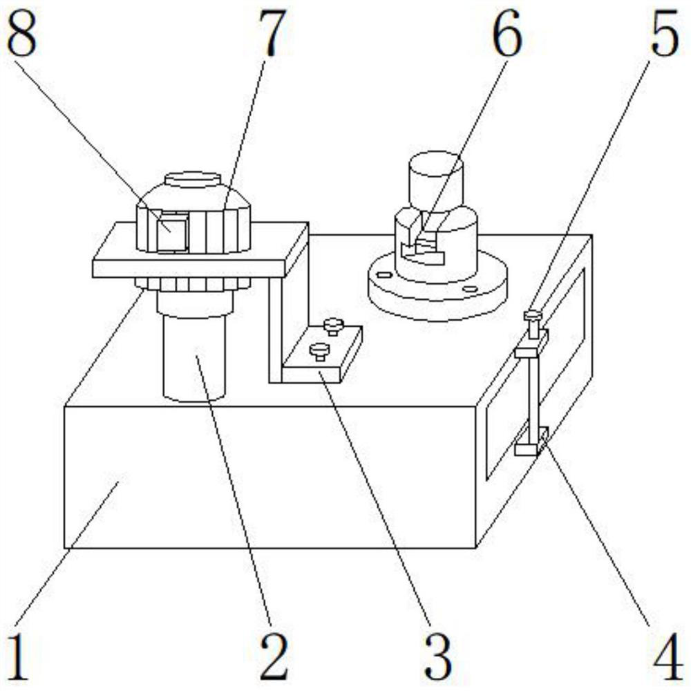
Figure 1 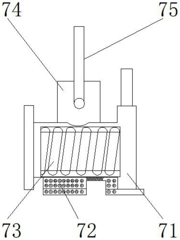
Figure 2 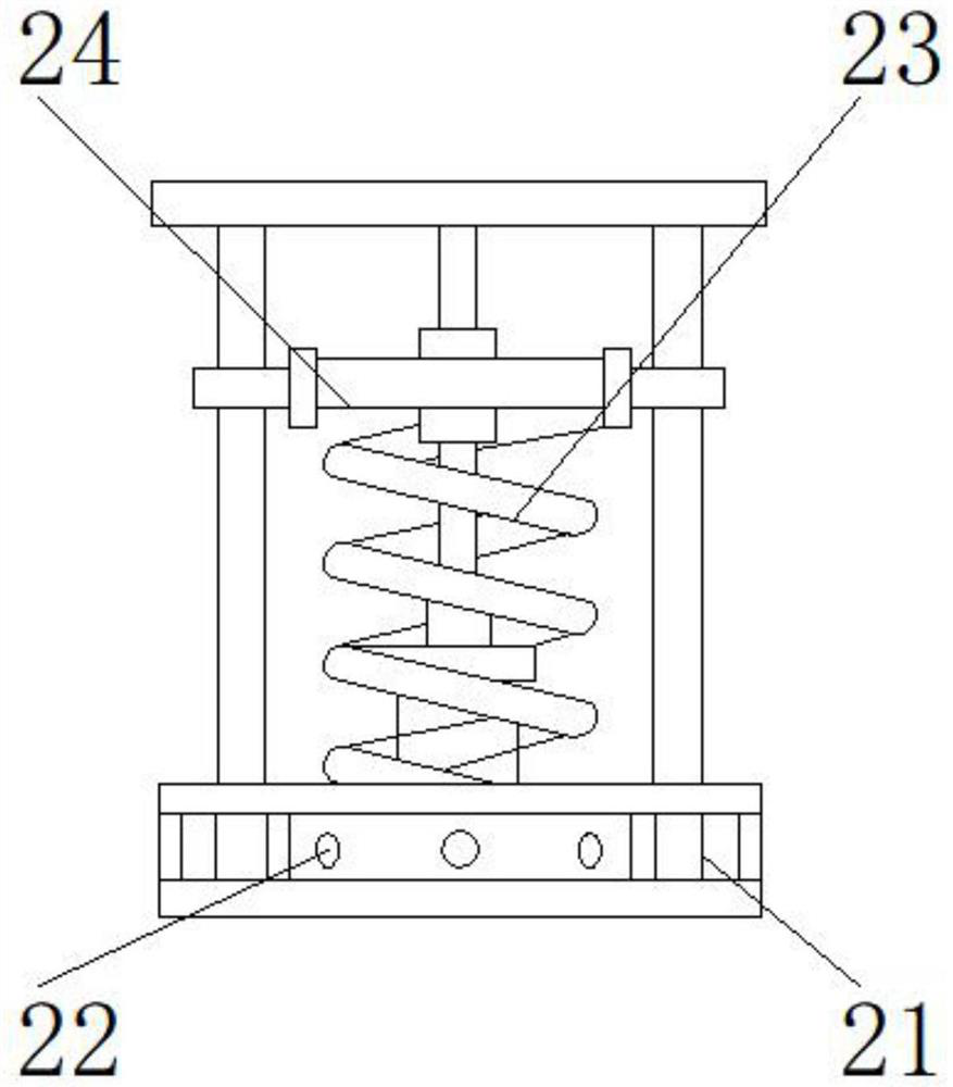
Figure 3
Abstract
Description
technical field
[0001] The invention relates to the field of electric power technology, in particular to an ultra-low temperature protection device for a high-voltage switch. Background technique
[0002] High-voltage switch refers to the power generation, transmission, distribution or power conversion of the power system. It is usually installed in a high-voltage switchgear. The switchgear has functions such as overhead incoming and outgoing lines, cable incoming and outgoing lines, and bus connection. , metallurgy and steel rolling, light industry textile and residential quarters, high-rise buildings and other places.
[0003] At present, the existing ultra-low temperature protection devices for high-voltage switches on the market are mainly improved for the damage of high-voltage switch insulation. For example, a kind of ultra-low temperature protection device for high-voltage switches provided by Chinese patent CN202797741 U has the ability to prevent the insulation gas ...
Examples
Embodiment 1
[0033] Such as Figure 1-8As shown, the present invention provides a high-voltage switch ultra-low temperature protection device, including a main body 1, the upper end of the main body 1 is provided with a ventilation device 2, the upper end of the ventilation device 2 is provided with an adjustment device 7, and the front end of the adjustment device 7 is provided with a controller 8 One side of the ventilation device 2 is provided with a protection device 3, one side of the protection device 3 is provided with a protection assembly 6, one side of the main body 1 is provided with a fixing device 5, and the lower part of the fixing device 5 is provided with an installation module 4; the ventilation device 2 comprises a chamber 21, a vent 22, a dust-proof net 23, and a dredging frame 24, the vent 22 is located at one side of the chamber 21, the dust-proof net 23 is positioned at the upper end of the vent 22, and the dredging frame 24 is positioned at the side of the dust-proof ...
Embodiment 2
[0036] Such as Figure 1-8 As shown, on the basis of Embodiment 1, the present invention provides a technical solution: preferably, the adjustment device 7 includes a driving device 71, a translation block 72, a lead screw 73, a slider 74, a vertical shaft 75, and a lead screw 73 Located on one side of the drive unit 71, the translation block 72 is located at the lower end of the drive unit 71, the slide block 74 is located at the upper end of the lead screw 73, the vertical shaft 75 is located at the upper end of the slide block 74, and the vertical shaft 75 is arranged between the slide block 74. Threaded groove is arranged, and the lower end of vertical rotating shaft 75 is detachably connected with the lower end of slide block 74 by threaded groove, is provided with interface between leading screw 73 and driving device 71, and one side of leading screw 73 passes through interface and one of driving device 71 The side is fixedly connected, and a chute is provided between th...
Embodiment 3
[0039] Such as Figure 1-8 As shown, on the basis of Embodiment 1, the present invention provides a technical solution: preferably, the fixing device 5 includes a stud bolt 51, a trapezoidal pressure plate 52, a shoulder nut 53, a stepped support 54, and the trapezoidal pressure plate 52 is located at the double The upper end of the head bolt 51, the shoulder nut 53 is located at the upper end of the trapezoidal pressing plate 52, the stepped support 54 is located at one side of the trapezoidal pressing plate 52, a notch is arranged between the stud bolt 51 and the trapezoidal pressing plate 52, the upper end of the stud bolt 51 The lower end of the trapezoidal pressing plate 52 is detachably connected through the notch, and a welding block is arranged between the trapezoidal pressing plate 52 and the stepped support 54. One side of the trapezoidal pressing plate 52 is fixedly connected with one side of the stepped support 54 through the welding block, and the trapezoidal press...