
Method and apparatus for lubricating cylinder surfaces in large diesel engines
A lubricating device and lubricating oil technology, which is applied in the field of lubricating systems, can solve problems such as high external injection pressure, and achieve the effect of a simple system
Patent Information
- Authority / Receiving Office
- CN · China
- Patent Type
- Patents(China)
- Current Assignee / Owner
- Publication Date
- 2010-06-02
Smart Images
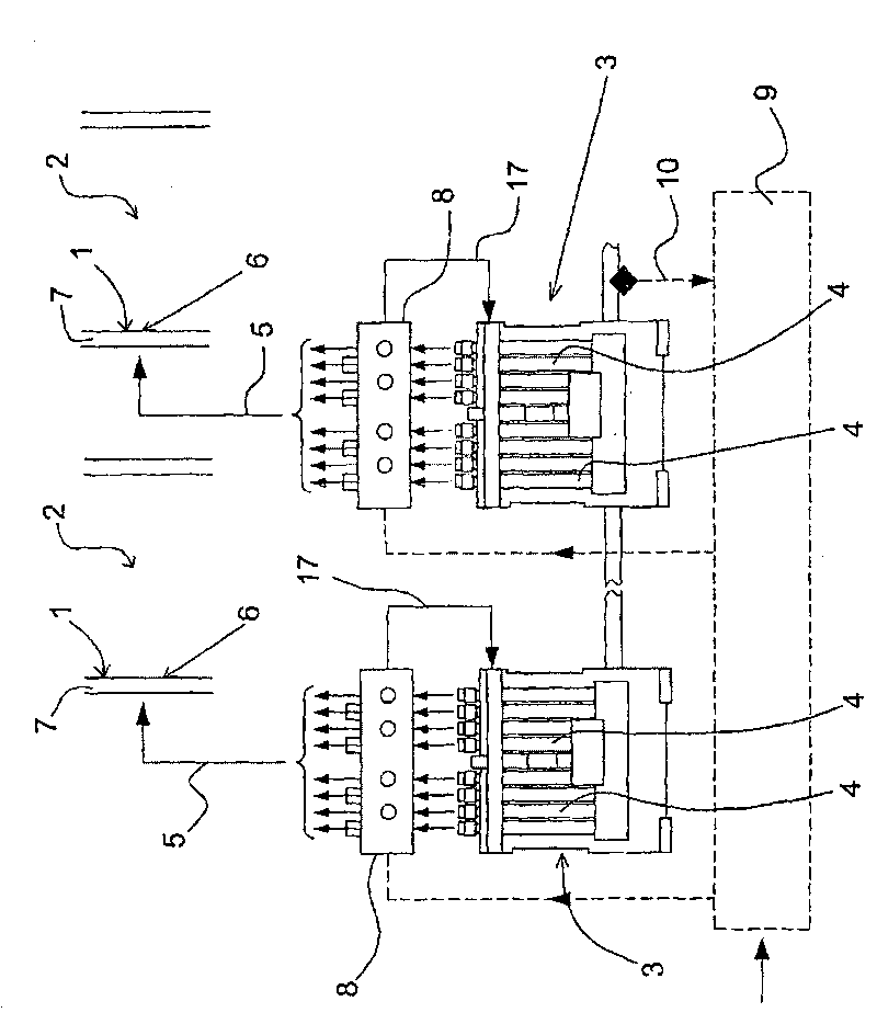
Figure 1 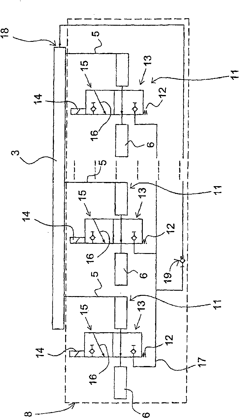
Figure 2 
Figure 3
Abstract
Description
technical field
[0001] The present invention relates to a lubricating system comprising a method and a device for lubricating the inner surface of a cylinder of a large diesel engine, in particular a marine engine, comprising at least one lubricating device having a plurality of piston pumps connected to the cylinder via connecting pipes The different lubrication points in the wall are connected together and supplied with lubricating oil. Background technique
[0002] The lubricating devices are usually designed as pump devices, which are fitted tightly to the respective cylinder and are connected to a reservoir for lubricating oil and to lubrication points in the form of oil spray nozzles at various points on the cylinder wall. Each pump unit comprises a plurality of piston pumps supplying lubricating oil to different lubricating points, and they are driven by a common rotating control shaft on which a cam is applied. As the shaft rotates, the cam with the extrusion head a...
Examples
Embodiment Construction
[0052] figure 1 Shown is an apparatus for lubricating the cylinder inner surface 1 of a cylinder 2 of a large diesel engine. The apparatus shown comprises two lubricating devices 3 each having a series of piston pumps indicated at 4 . Via connecting pipes 5 (only one is shown for each lubricating device), each piston pump is connected to a lubrication point 6 provided in the cylinder wall 7 for lubricating the cylinder inner surface 1 of the cylinder wall. The device also includes a flow regulator 8, which will refer to figure 2 Describe in detail.
[0053] Furthermore, the device comprises an electronic control unit 9 connected to the flow regulator 8 and the lubricating device 3 . As indicated at 10 , the flow regulator may receive an indication signal from the lubricating device 3 .
[0054] figure 2 is a schematic diagram of the flow regulator 8 . figure 2 Three lubrication points 6 and a lubrication device 3 are shown. This state therefore shows that there are t...