
Encoder, associated encoding method and flash memory controller
a flash memory controller and encoder technology, applied in the field of encoders, can solve the problems of increasing the complexity of the encoder, the inability to find the parity generator matrix under some conditions, and the increase of the hardware cost of the encoder, so as to achieve the effect of increasing the hardware cos
Patent Information
- Authority / Receiving Office
- US · United States
- Patent Type
- Patents(United States)
- Current Assignee / Owner
- Publication Date
- 2020-10-20
Smart Images
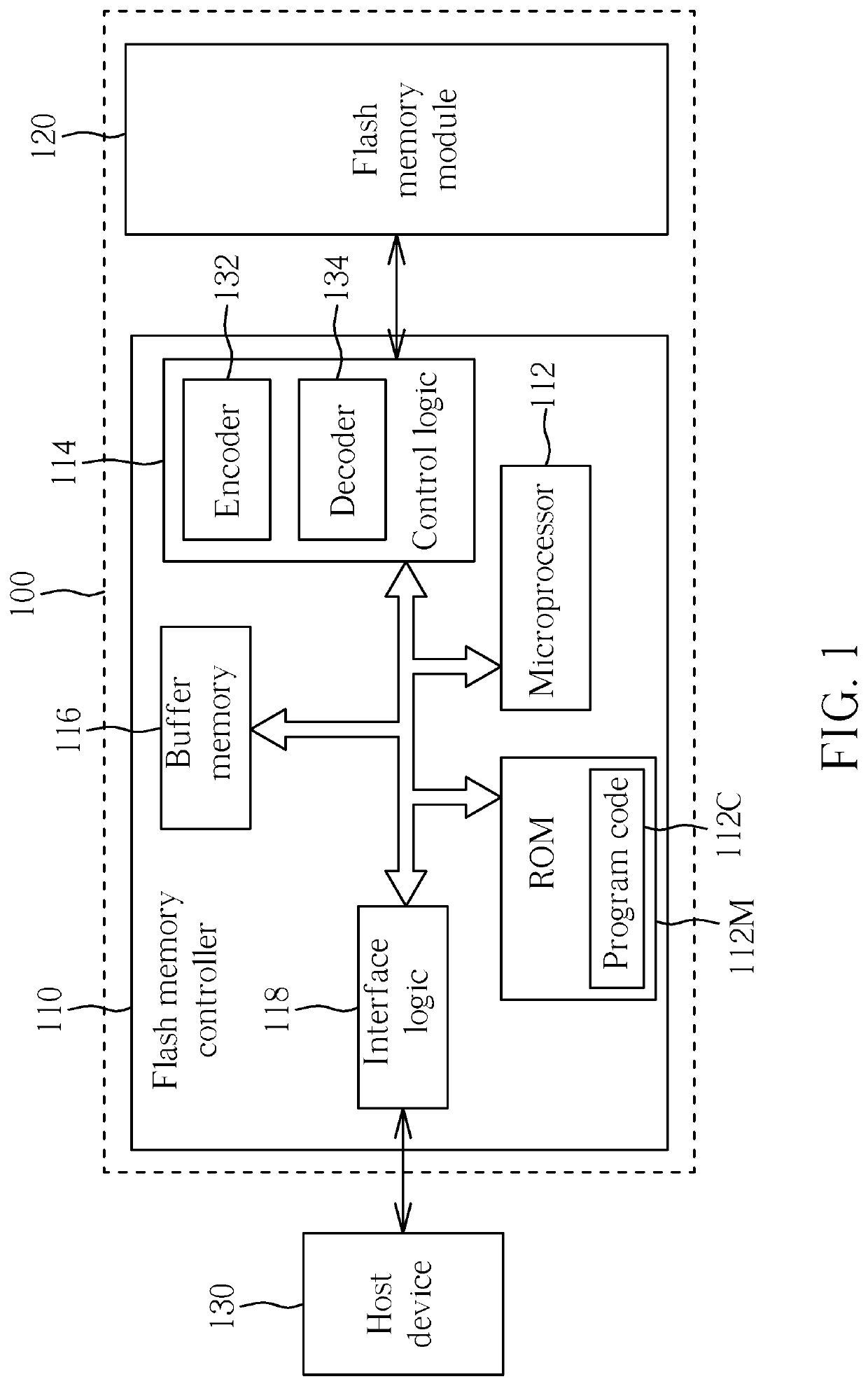
Figure 1 
Figure 2 
Figure 3
Abstract
Description
BACKGROUND OF THE INVENTION1. Field of the Invention
[0001] The present invention is related to encoders, and more particularly, to an encoder for a flash memory controller, an associated encoding method, and an associated flash memory controller.2. Description of the Prior Art
[0002] A general encoder may have a parity-check matrix in order to check whether the parity generated by the encoder is correct. For example, after the encoder encodes data to generate parity (e.g. check code), the encoder may multiply the data and the parity by this parity-check matrix, where if the multiplication result is “0”, the encoding is determined to be correct; otherwise, the encoding is determined to be incorrect. In response to this parity-check matrix, the encoder may have a corresponding parity generator matrix in order to generate appropriate parity. The parity generator matrix is not able to be found under some conditions, however. The encoder may need to perform multiple matrix multiplying opera...
Examples
Embodiment Construction
[0013]FIG. 1 is a diagram illustrating a memory device 100 according to an embodiment of the present invention. The memory device 100 comprises a flash memory module 120 and a flash memory controller 110, and the flash memory controller 110 is arranged to access the flash memory module 120. According to this embodiment, the flash memory controller 110 comprises a microprocessor 112, a read only memory (ROM) 112M, a control logic 114, a buffer memory 116 and an interface logic 118. The ROM 112M is arranged to store a program code 112C, and the microprocessor 112 is arranged to execute the program code 112C to control access to the flash memory module 120. The control logic 114 comprises an encoder 132 and a decoder 134, where the encoder 132 is arranged to encode data that is written into the flash memory module 120 to generate a corresponding check code (or error correction code (ECC)), and the decoder 134 is arranged to decode data that is read out from the flash memory module 120....