
Overmolded body for bar feeder
a feeder body and overmolded technology, applied in the field of overmolded body feeders, can solve the problems of high assembly time, low yield, and low overall precision of guiding provided, and achieve the effect of improving the conferred anti-vibration and anti-noise properties and good density
Patent Information
- Authority / Receiving Office
- US · United States
- Patent Type
- Patents(United States)
- Current Assignee / Owner
- Publication Date
- 2021-08-31
Smart Images
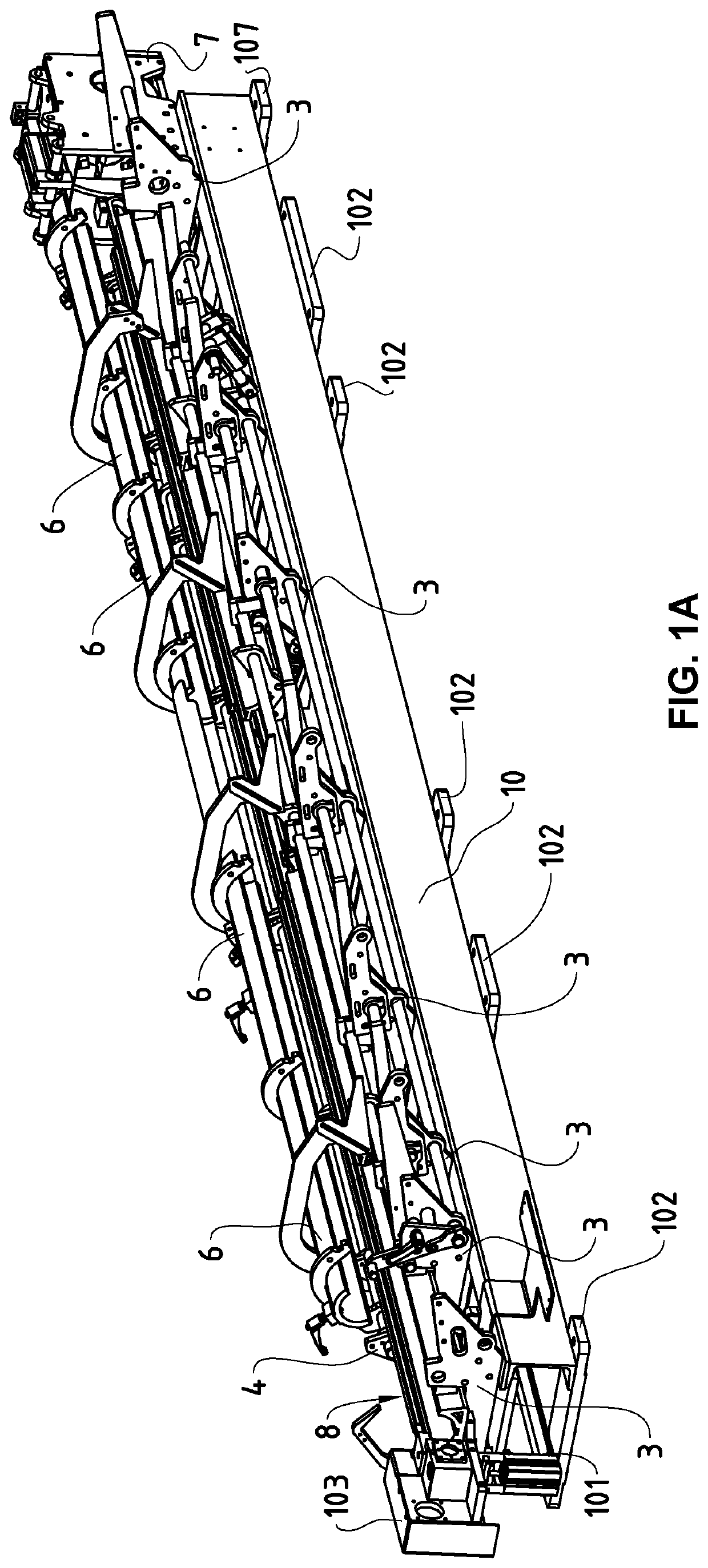
Figure 1 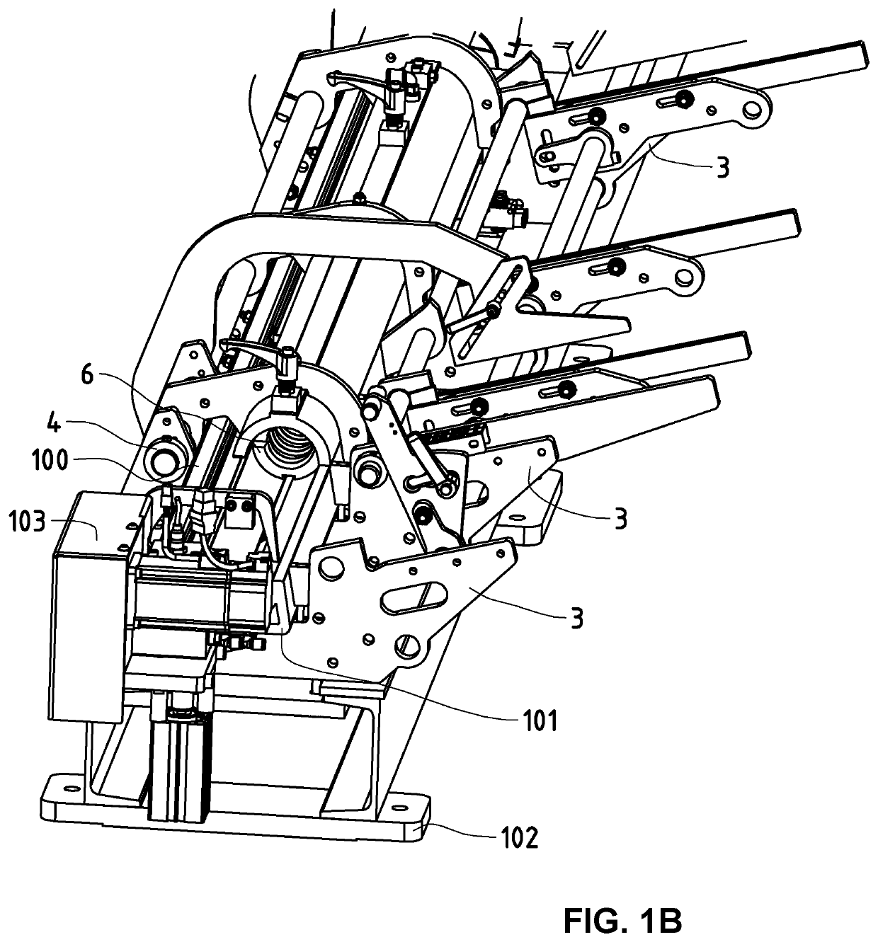
Figure 2 
Figure 3
Abstract
Description
TECHNICAL FIELD OF THE INVENTION
[0001] This invention relates to the field of bar feeders. More specifically, it concerns a method of producing a body, preferably made using polymer concrete, as well as a body obtained by such a production method for bar feeders.STATE OF THE ART
[0002] The use of polymer concrete is known for machine tools as the filling material of hollow structures, permitting notably to increase the mass and to reinforce the rigidity, and also to damp the vibrations better during their use. The patent document EP1683602 describes such an example of a machine tool whose framework is partially filled with polymer concrete. No structural element nor even less so functional element, is made however using the polymer concrete whose purpose is merely to ballast and make rigid pre-existing structures.
[0003] In the more specific context of bar feeders, intended, for example, to route bars to be machines by automatic lathes positioned downstream from the chain of production, ...
Examples
Embodiment Construction
[0025]FIGS. 1A and 1B illustrate two schematic views in three dimensions of a bar feeder according to the prior art, mounted on a body constituted by a box 10 of metal, at the base of which are arranged fixation clamps 102 provided for assembly of the feet placed on the floor. The bar feeder is represented in two different functional positions, i.e. a first position (FIG. 1A) in which the bearings 6 are in open position, then a second position (FIG. 1B) in which the bearings 6 are closed. The structure of the body of this bar feeder is structured around a central beam of metal 100, visible in FIG. 1B, which is commonly referred to as “beam”, and to which are fixed different anchoring elements 3 and on which are mounted different segments of a section in aluminum 101 inside which are mounted the elements for guiding of the formed bars by the bearings 6. According to the disclosure illustrated in this figure, these bearings 6 are in fact constituted by two shells of identical shape, h...