
Device for injecting fuel to stationary internal combustion engines
a technology for injecting devices and internal combustion engines, which is applied in the direction of fuel injecting pumps, liquid fuel feeders, machines/engines, etc., can solve the problems of high pressure building up between the pump unit, design cannot completely eliminate cavitation defects, and the stable pressure level of the accumulator of the other fuel injectors is undisturbed
Patent Information
- Authority / Receiving Office
- US · United States
- Patent Type
- Applications(United States)
- Current Assignee / Owner
- Publication Date
- 2004-09-30
- Estimated Expiration
- Not applicable · inactive patent
Smart Images
Figure 1 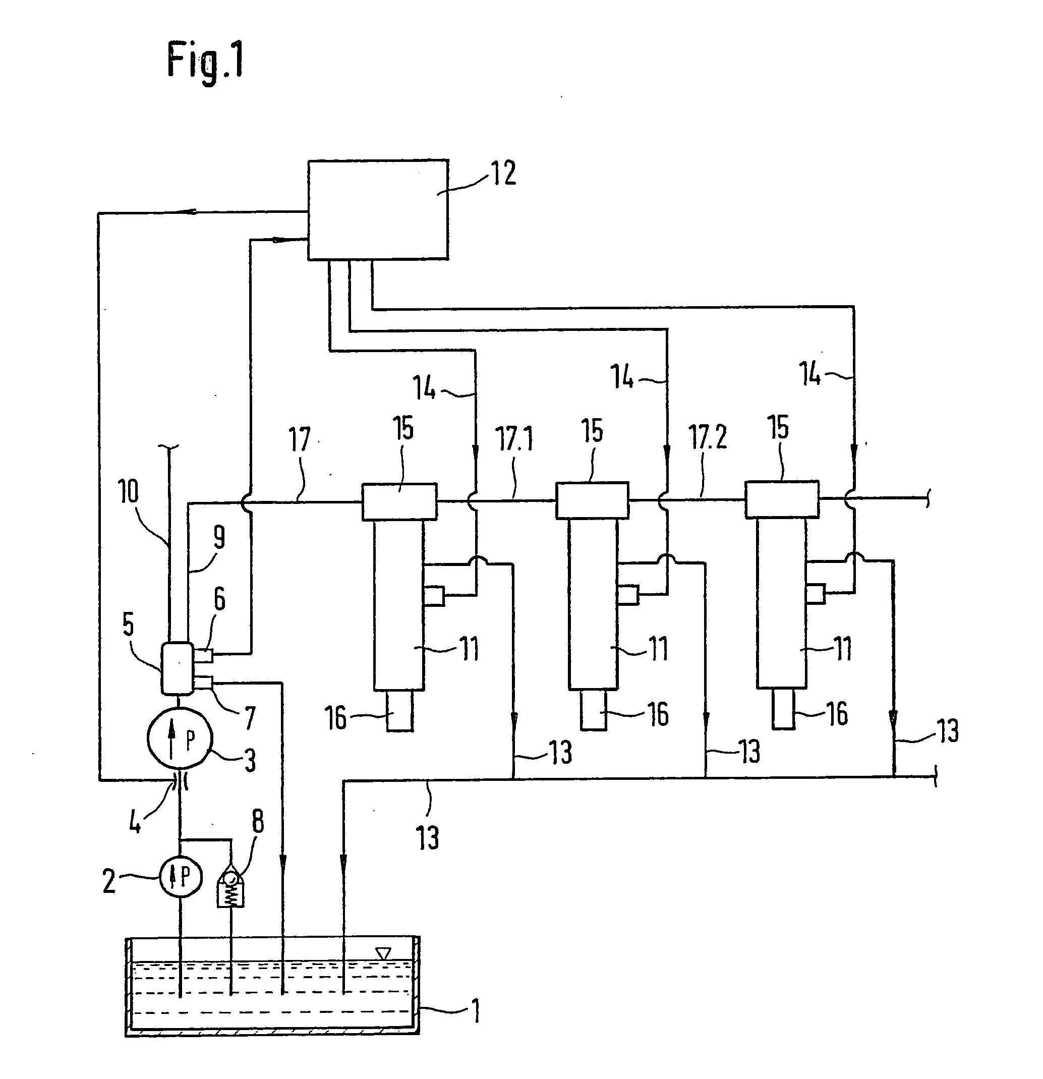
Figure 2 
Figure 3
Abstract
Description
[0001] Internal combustion engines that are used as vehicle motors, stationary motors (generator motors), or for propelling ships as a rule have between 2 and 20 cylinders. In these engines, the bore diameter of the respective cylinders lies within a broad spectrum, sometimes reaching 500 mm in large diesel engines. Depending on the number of cylinders, individually customized fuel injection systems are used, which must be individually tailored to the number of cylinders.
[0002] 1. Prior Art
[0003] DE 198 37 332 A1 relates to a control unit for controlling the buildup of pressure in a pump unit. The control unit has a control valve with a valve-actuating unit connected to it. The control valve is embodied as an I-valve that opens inward in the flow direction and has a valve body that is supported so that it can slide axially in housing of the control unit and when the control valve is closed, rests against a valve seat of the control valve from the inside. A throttle device is provide...
Examples
Embodiment Construction
[0021] FIG. 1 shows the components of an injection system.
[0022] The injection system shown in FIG. 1, which is for supplying fuel to an internal combustion engine, includes a fuel reservoir 1. A fuel-supply pump 2 delivers fuel from the fuel reservoir 1. On the pressure side, the fuel-supply pump 2 has a high-pressure pump unit 3 connected downstream of it, which is preceded by a throttle restriction 4. The throttle restriction 4 is designed to be variable and can be triggered by means of a control unit 12. The fuel-supply pump 2 has a pressure control valve 8 connected downstream of it, which controls the supply pressure to the high-pressure pump unit 3 and is connected to the fuel reservoir 1.
[0023] The high-pressure pump unit 3 includes an integrated pressure accumulator 5. A pressure relief valve 7 whose outlet feeds into the fuel reservoir 1 protects the pressure accumulator 5. The integrated pressure accumulator 5 also has a pressure sensor 6, which is connected to the contro...