
Monolithic pour joint
a monolithic, pour joint technology, applied in the direction of roads, constructions, paving details, etc., can solve the problems of small decrease in the overall volume of concrete, cracks may occur, large cracks may develop in concrete, etc., to prevent buckling or relative angular or vertical displacement of slabs, prevent unevenness or steps
Patent Information
- Authority / Receiving Office
- US · United States
- Patent Type
- Applications(United States)
- Current Assignee / Owner
- Publication Date
- 2005-02-17
- Estimated Expiration
- Not applicable · inactive patent
Smart Images
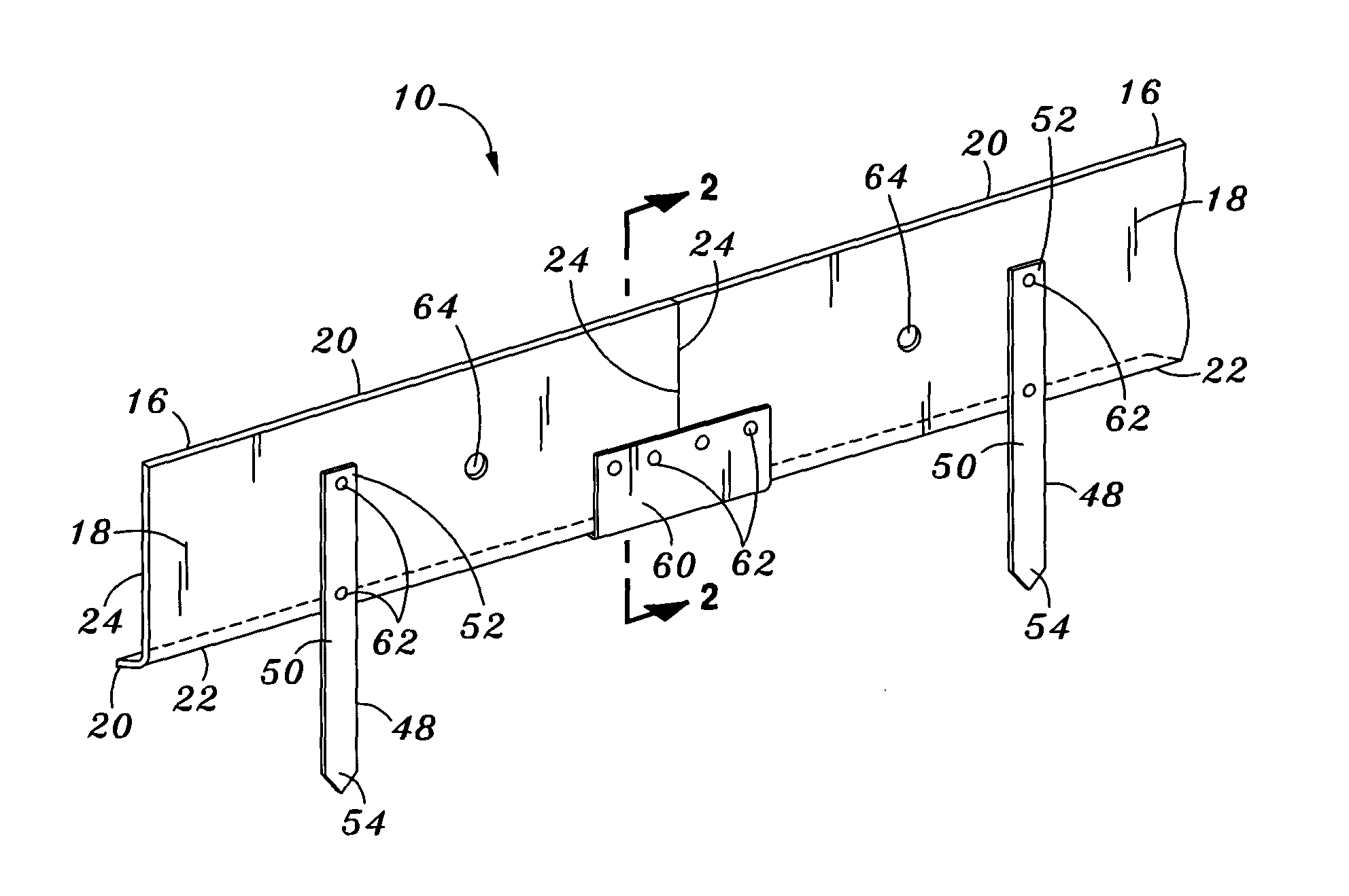
Figure 1 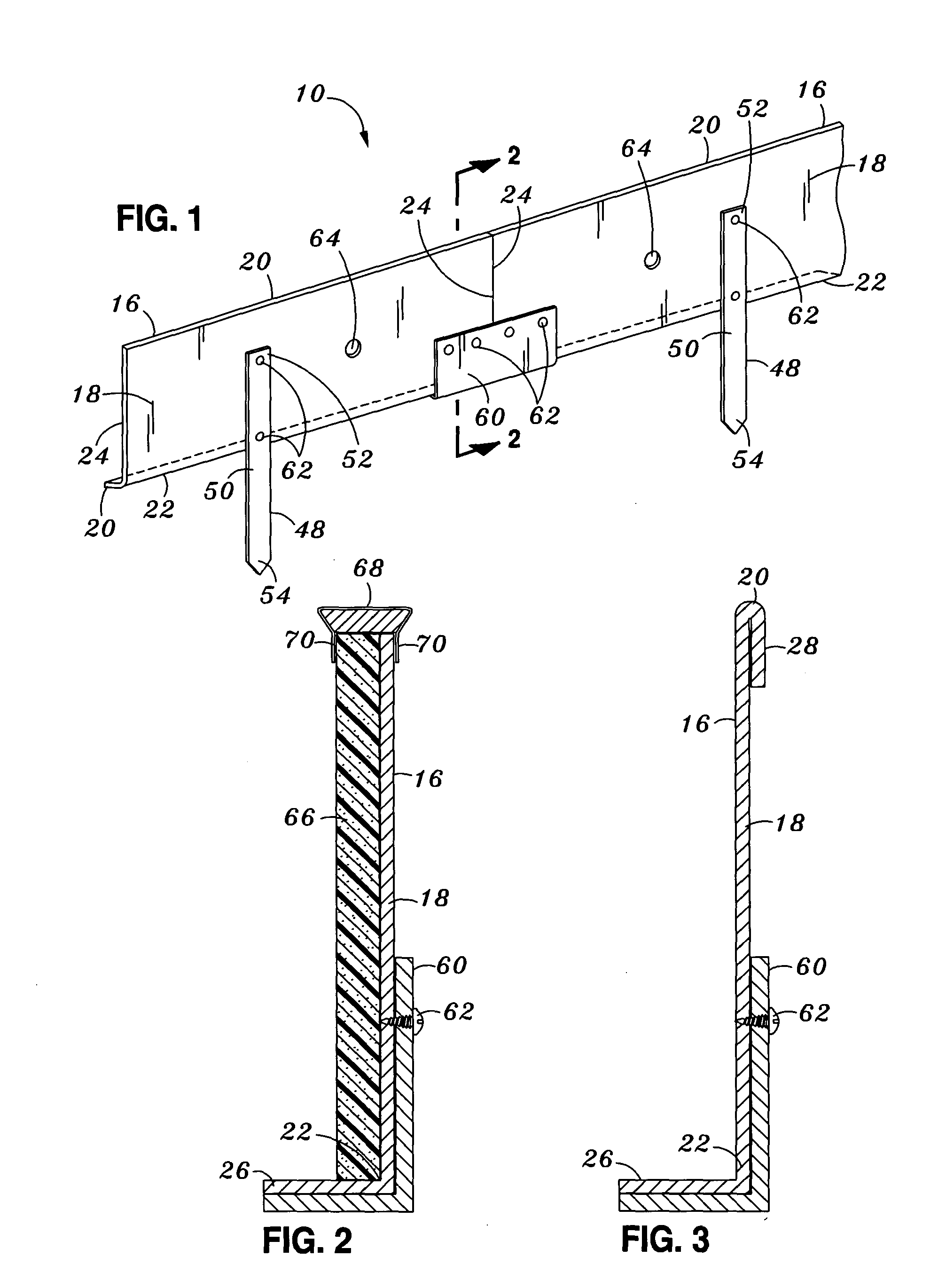
Figure 2 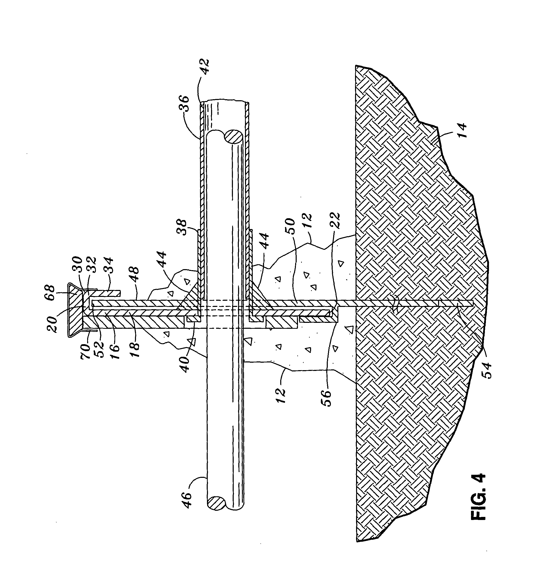
Figure 3
Abstract
Description
CROSS-REFERENCE TO RELATED APPLICATIONS
[0001] (Not Applicable) STATEMENT RE: FEDERALLY SPONSORED RESEARCH / DEVELOPMENT
[0002] (Not Applicable) BACKGROUND OF THE INVENTION
[0003] The present invention relates generally to concrete forming equipment and, more particularly, to a uniquely configured monolithic pour joint specifically adapted to prevent shear cracking of adjacently disposed concrete slabs. The pour joints are configured to facilitate the placement of dowel rods within adjacent concrete slabs.
[0004] During construction of concrete pavement such as for sidewalks, driveways, roads and flooring in buildings, cracks may occur due to uncontrolled shrinkage or contraction of the concrete. Such cracks are the result of a slight decrease in the overall volume of the concrete as water is lost from the concrete mixture during curing. Typical contraction rates for concrete are about one-sixteenth of an inch for every ten feet of length. Thus, large cracks may develop in concrete wh...
Examples
Embodiment Construction
[0028] Referring now to the drawings wherein the showings are for purposes of illustrating preferred embodiments of the present invention and not for purposes of limiting the same, FIG. 1 illustrates a monolithic pour joint 10 of the present invention wherein the pour joint 10 may be interposed between concrete slabs 12 that are disposed above a subgrade or a substrate 14. The substrate 14 may be soil underlying the slab. Alternatively, the substrate 14 may be a metal decking or other underlying surface adapted to support concrete slabs 12. The pour joint 10 is comprised of at least one elongate form 16 or a plurality of forms 16 arranged in end-to-end alignment with a splice 60 interconnecting the forms 16 and a plurality of elongate stakes 48 secured to a side of the forms 16 to fixedly maintain or support the forms 16 above the substrate 14.
[0029] Each of the forms 16 includes a substantially planar, vertical panel 18 having an upper edge 20 and a lower edge 22 to define a form ...