
Multi-view integrated camera system
Patent Information
- Authority / Receiving Office
- US · United States
- Current Assignee / Owner
- Publication Date
- 2006-02-02
Smart Images
Figure 1 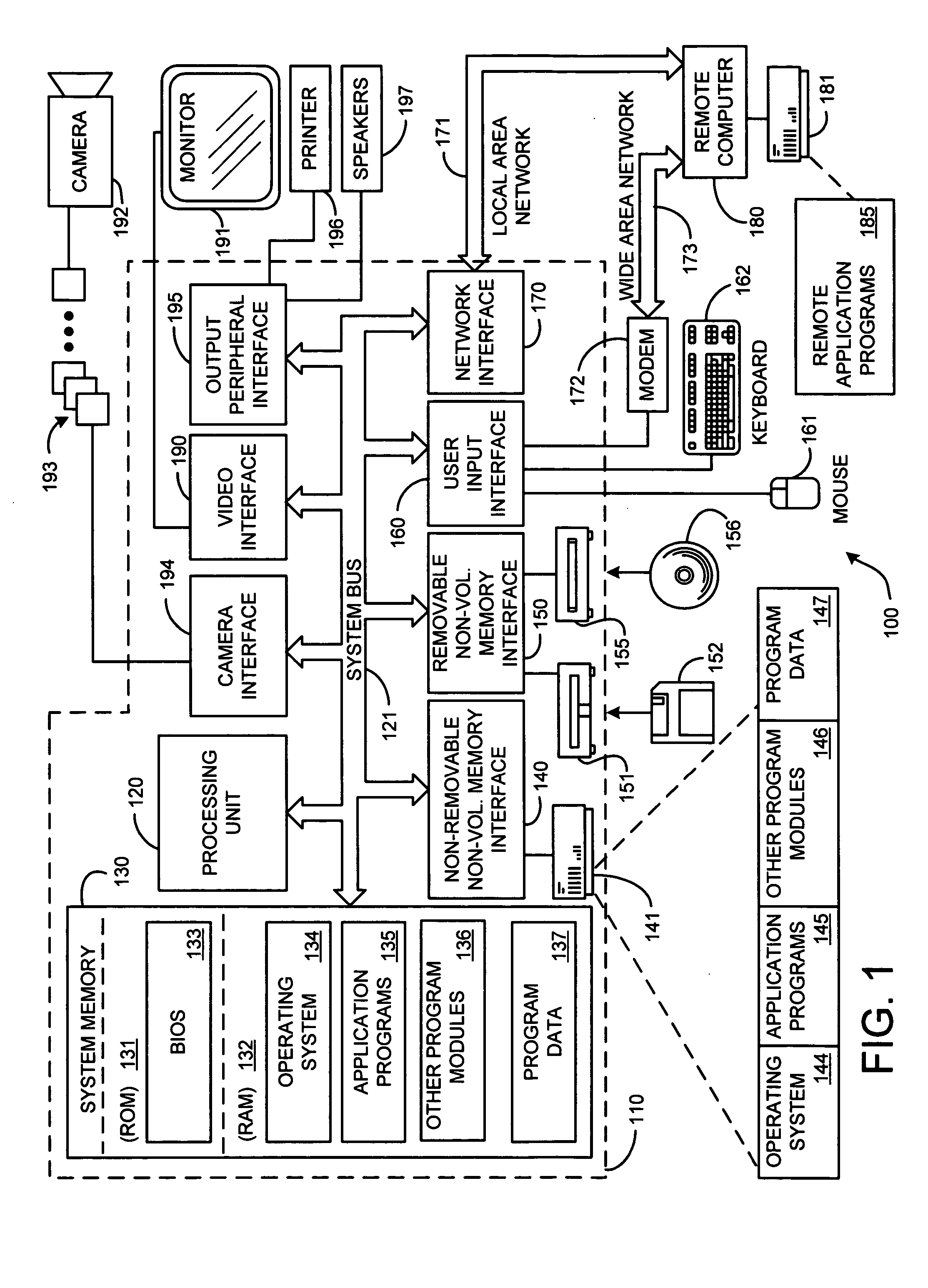
Figure 2 
Figure 3
Abstract
Description
BACKGROUND
[0001] 1. Technical Field
[0002] This invention is directed toward a new camera design. More specifically, this invention is directed toward a new omni-directional camera design that makes use of a unified molded structure of optical material to house a mirror, aligned sensor, and lens assembly.
[0003] 2. Background Art
[0004] Video conferencing systems have had limited commercial success. This is due to many factors. In many cases video conferencing systems are too expensive for individuals and small businesses to afford. Additionally, there are numerous technical deficiencies in the video conferencing systems to date. Poor camera viewpoints and insufficient image resolution make it difficult for meeting participants to see the person speaking. This is compounded by the fact that many camera systems are difficult for the user to operate. Cameras for video conferencing systems are sometimes very delicate and can be damaged by an untrained user trying to adjust the camera ...
Examples
Embodiment Construction
[0024] In the following description of the preferred embodiments of the present invention, reference is made to the accompanying drawings that form a part hereof, and in which is shown by way of illustration specific embodiments in which the invention may be practiced. It is understood that other embodiments may be utilized and structural changes may be made without departing from the scope of the present invention.
1.0 Exemplary Operating Environment
[0025]FIG. 1 illustrates an example of a suitable computing system environment 100 on which the invention may be implemented. The computing system environment 100 is only one example of a suitable computing environment and is not intended to suggest any limitation as to the scope of use or functionality of the invention. Neither should the computing environment 100 be interpreted as having any dependency or requirement relating to any one or combination of components illustrated in the exemplary operating environment 100.
[0026] The i...