
Camera system and camera body
a camera system and camera body technology, applied in the field of camera systems and camera bodies, can solve the problems of difficult to make the release time lag short consistent, lose the advantage of vibration compensation, and increase etc., to achieve the effect of reducing the range over which vibration compensation can be performed during photography, and reducing the loss of vibration compensation
Patent Information
- Authority / Receiving Office
- US · United States
- Current Assignee / Owner
- Publication Date
- 2009-01-01
- Estimated Expiration
- Not applicable · inactive patent
Smart Images
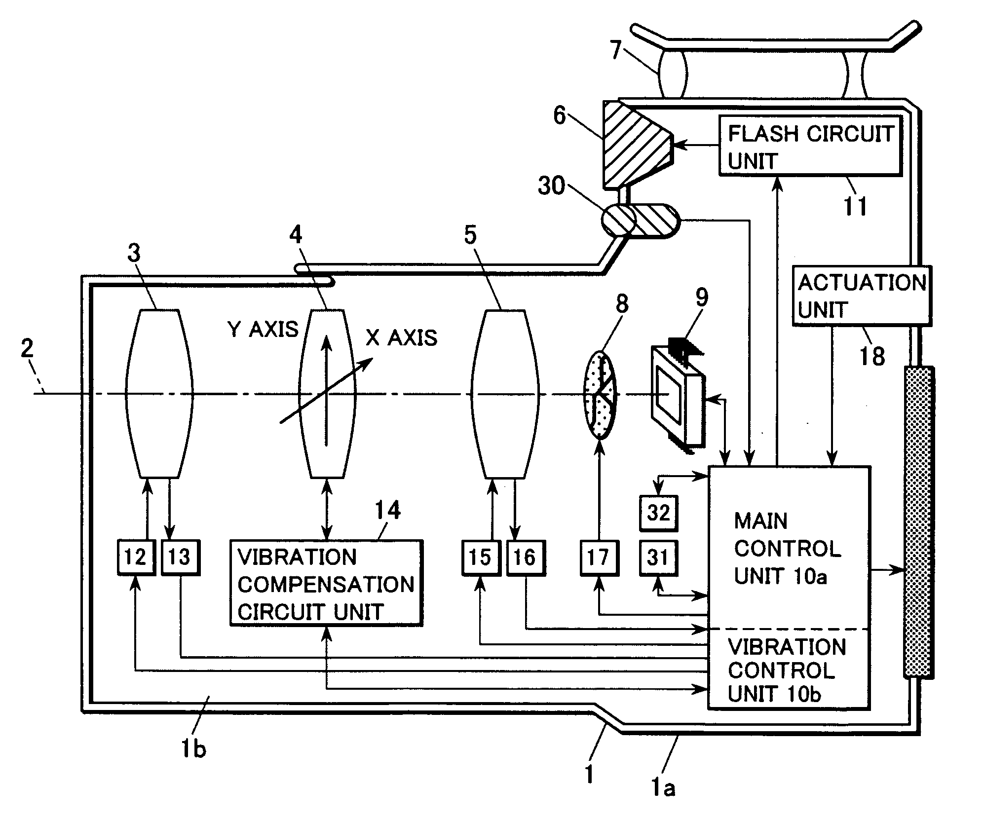
Figure 1 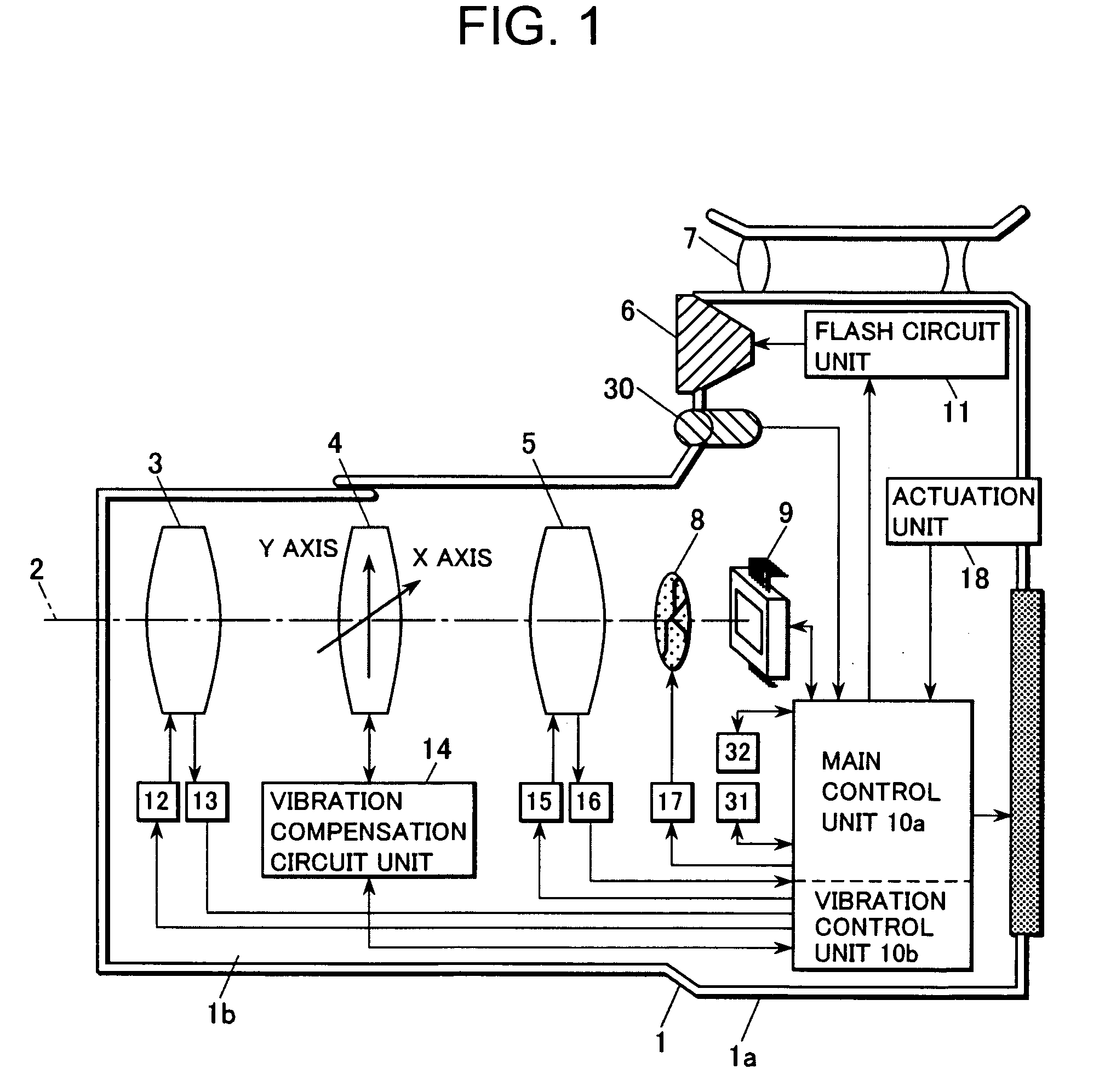
Figure 2 
Figure 3
Abstract
Description
INCORPORATION BY REFERENCE
[0001] The disclosures of the following priority applications are herein incorporated by reference:
[0002] Japanese Patent Application No. 2007-036062, filed Feb. 16, 2007; and
[0003] Japanese Patent Application No. 2007-036156, filed Feb. 16, 2007.BACKGROUND OF THE INVENTION
[0004] 1. Technical Field
[0005] The present invention relates to a camera system and a camera body that can prevent image vibration that originates in camera vibration and the like.
[0006] 2. Description of Related Art
[0007] In Japanese Laid-Open Patent Publication 2001-209084, there is disclosed a vibration compensation device that detects an amount of vibration based upon the angular velocity with which a camera vibrates, or upon the vibration of the image, and that compensates vibration of an image capture surface or of a film surface by driving a vibration compensation lens according to this amount of vibration that has been detected. With this type of vibration compensation device, the vibra...
Examples
first embodiment
The First Embodiment
1-1 Explanation of the Overall Structure
[0053]FIG. 1 is a block diagram showing a camera that is equipped with a vibration compensation device according to the present invention. Here, the concrete example given is a digital still camera. This camera 1 includes a zoom lens 3, a compensation lens 4, a focusing lens 5, a flash unit 6, an optical viewfinder 7, a shutter 8, an image sensor 9, a control unit 10, a flash circuit unit 11, a zoom lens drive unit 12, a zoom lens position detection unit 13, a vibration compensation circuit unit 14, a focusing lens drive unit 15, a focusing lens position detection unit 16, a shutter drive unit 17, an actuation unit 18, an external liquid crystal monitor 19, a sound gathering unit 30, a non-volatile storage medium 31, and an actuation sound generation unit 32.
[0054]The control unit 10 consists of a one chip micro computer and so on, and undertakes overall control of this camera 1. This control unit 10, functionally, is divid...
second embodiment
The Second Embodiment
[0305]In the first embodiment described above, it was arranged to cancel out vibration acting upon the image sensor 9 by driving the compensation lens 4, that constitutes one portion of the photographic optical system, to shift in some direction in a plane orthogonal to the photographic optical axis 2, according to the camera vibration as obtained by the vibration gyros 200a and 200b; but, with regard to the method for image vibration compensation, the system is not to be considered as being limited to this type of structure. FIG. 19 is a block diagram showing a second embodiment of a camera according to the present invention. With the camera shown in FIG. 19, for an image vibration amount that is generated by the photographic optical axis 2 changing due to camera vibration, it is arranged to perform image vibration compensation by shifting the image sensor 9 itself. It should be understood that, in FIG. 9, the same numbers are appended to portions of the struct...
third embodiment
The Third Embodiment
[0309]Furthermore, the camera according to the present invention is not limited to being a digital still camera as described above, in particular to being a compact digital still camera; the present invention could also be applied to a silver halide film camera, or to a single lens reflex camera. FIG. 20 is a figure showing an example in which the present invention has been applied to a digital single lens reflex camera system. The camera 701 shown in FIG. 20 includes a body portion 701a and a lens portion 701b that is made so as to be removable therefrom.
[0310]The relationship between the digital single lens reflex camera system shown in FIG. 20 and the previously described compact digital still camera shown in FIG. 1 (the camera 1) is as follows. That is, elements of the camera 701 shown in FIG. 20 correspond to elements of the camera 1 shown in FIG. 1 in the following manner: a body portion 701a to the body 1a; a lens portion 701b to the lens-barrel 1b; a phot...