
Cooling plate for an iron- or steelmaking furnace
a technology of cooling plate and iron ore, which is applied in the direction of chamber doors, laminated elements, light and heating apparatus, etc., can solve the problems of inability to achieve far, and achieve the effects of reducing pressure loss, avoiding discontinuities in flow patterns, and pre-determined pressure losses in individual cooling circuits
Patent Information
- Authority / Receiving Office
- US · United States
- Patent Type
- Applications(United States)
- Current Assignee / Owner
- Publication Date
- 2009-08-20
- Estimated Expiration
- Not applicable · inactive patent
Smart Images
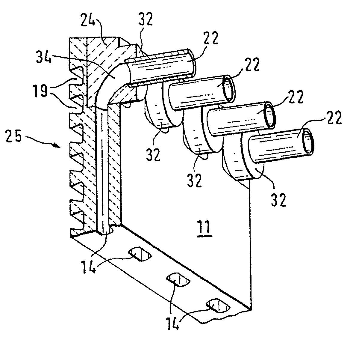
Figure 1 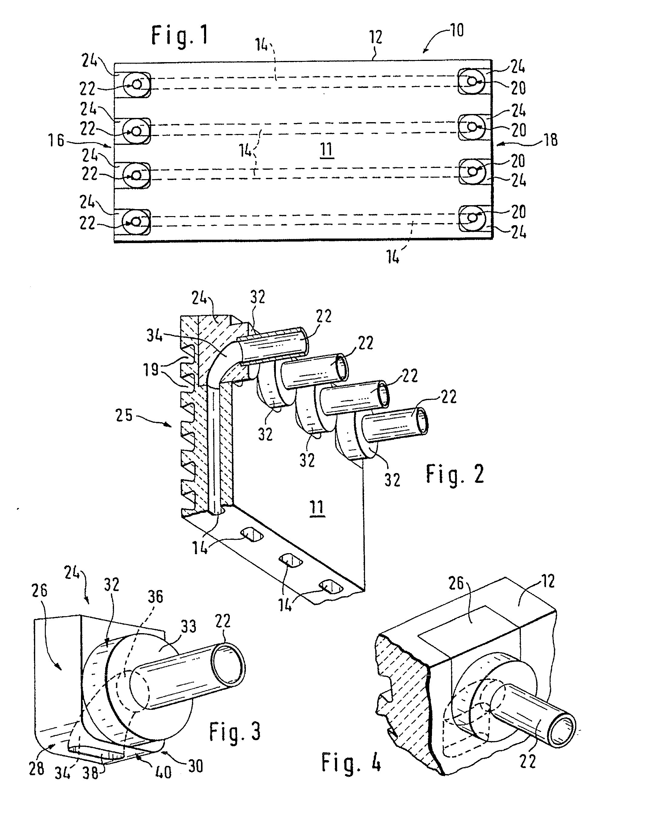
Figure 2 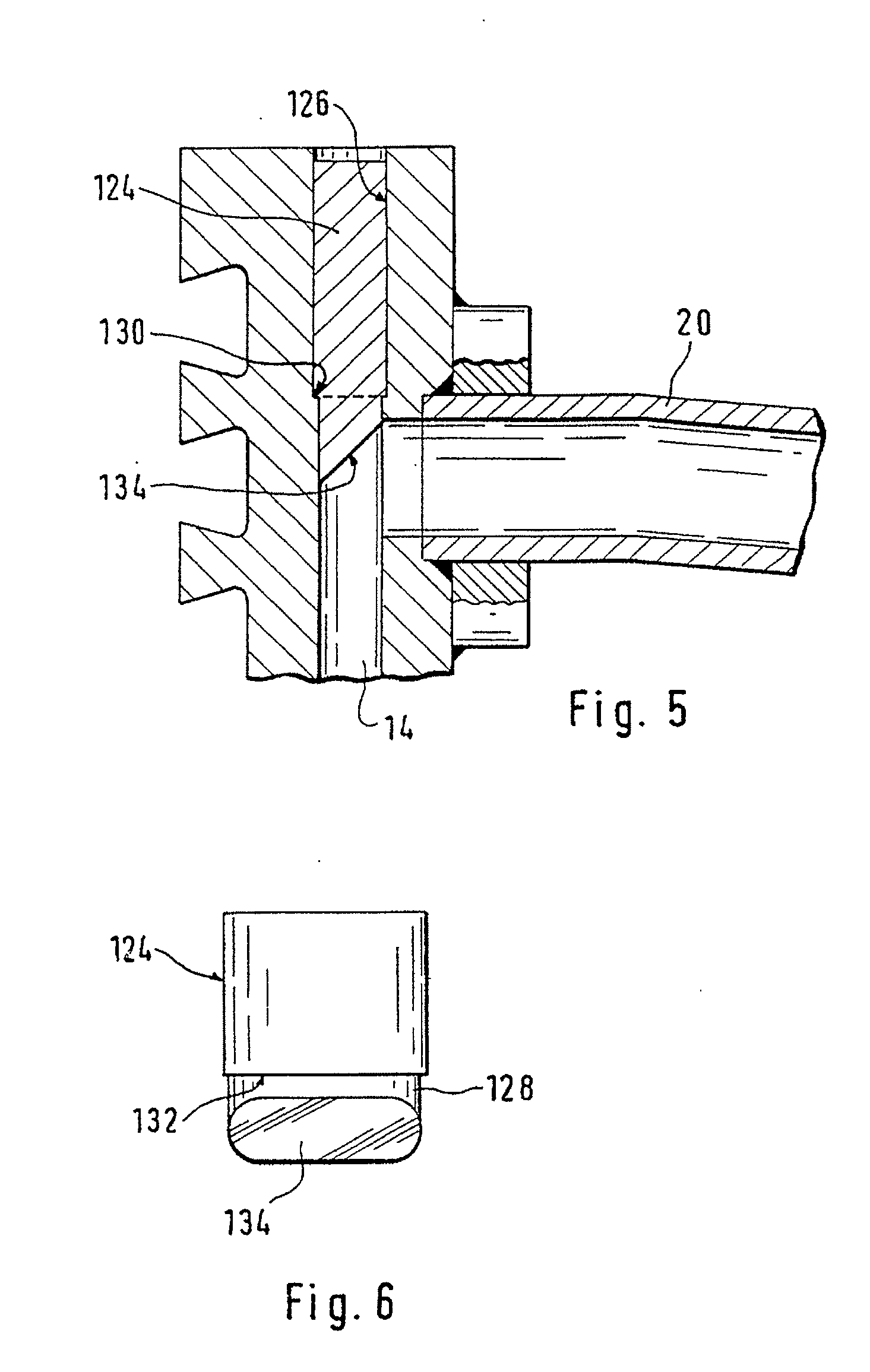
Figure 3
Abstract
Description
CROSS REFERENCE TO RELATED APPLICATIONS
[0001] This application is entitled to the benefit of International Application No. PCT / EP1999 / 08735, filed on Nov. 12, 1999, Luxembourg Patent Application No. LU 90328, filed on Dec. 16, 1998 and is a Divisional application of U.S. Non-Provisional Application No. Ser. No. 09 / 868,117, filed on Aug. 20, 2001, now U.S. Pat. No. ______.FIELD OF THE INVENTION
[0002] The invention relates to a cooling plate for an iron- or steelmaking furnace.BACKGROUND OF THE INVENTION
[0003] Such cooling plates are arranged on the inside of the furnace shell and have internal cooling ducts. These cooling plates are connected via connection pieces projecting from their back to a cooling system of the shaft furnace outside the furnace shell. Their surface facing the interior of the furnace is generally lined with a refractory material.
[0004] Most of these cooling plates are still made from cast iron. As copper has a far better thermal conductivity than cast iron; however,...
Examples
Embodiment Construction
[0032]The cooling plate 10 shown consists essentially of a cooling plate body 12 made from copper or a copper alloy with a rectangular surface. Four straight cooling ducts 14, which extend parallel with the surface through the cooling plate body 12 from one end 16 to the opposite end 18, are integrated in the cooling plate body 12. This cooling plate body 12 was advantageously manufactured by the method described in the subsequently published patent application WO 98 / 30345. A preform of the cooling plate body 12 was continuously cast in a continuous casting mould, whereby rod-type inserts in the casting duct produced ducts running in the casting direction, which form the cooling ducts 14. As shown in FIG. 2 the cross-section of the integrally cast ducts 14 has an oblong shape with its smallest dimension at right angles to the plate. A plate was cut out of this continuously cast preform by two cuts at right angles to the casting direction, the two end faces 16 and 18 of the cooling p...