
Universal projector interface with sustainable alignment
a projector and sustainable alignment technology, applied in the direction of instruments, counting objects on conveyors, machine supports, etc., can solve the problems of difficult positioning, impromptu arrangements, and difficulty in positioning portable projectors, etc., to achieve easy and fast adaptability, projector mounting, and easy serviceability
Patent Information
- Authority / Receiving Office
- US · United States
- Patent Type
- Applications(United States)
- Current Assignee / Owner
- Publication Date
- 2009-12-24
Smart Images
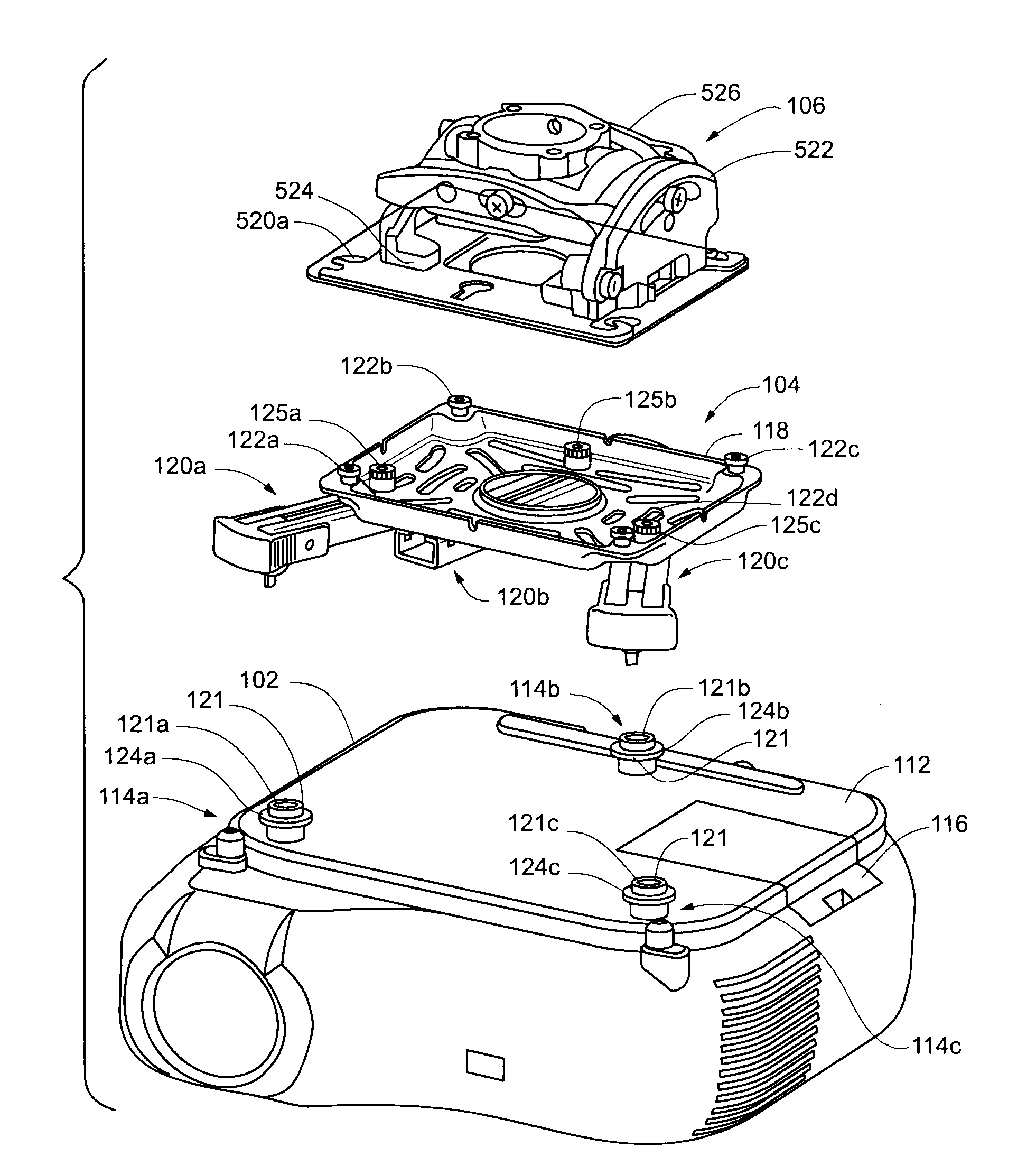
Figure 1 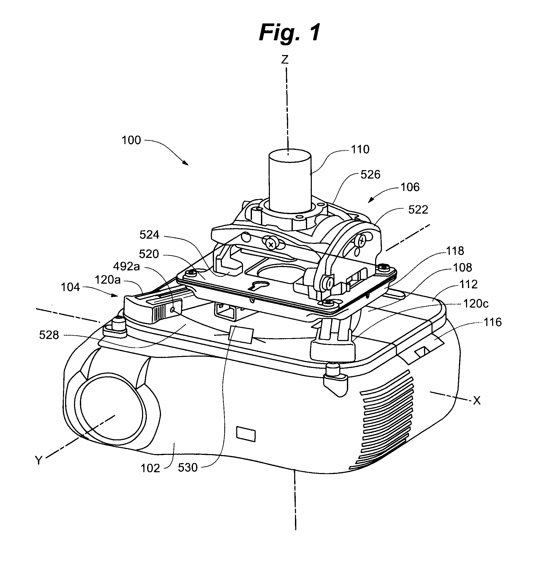
Figure 2 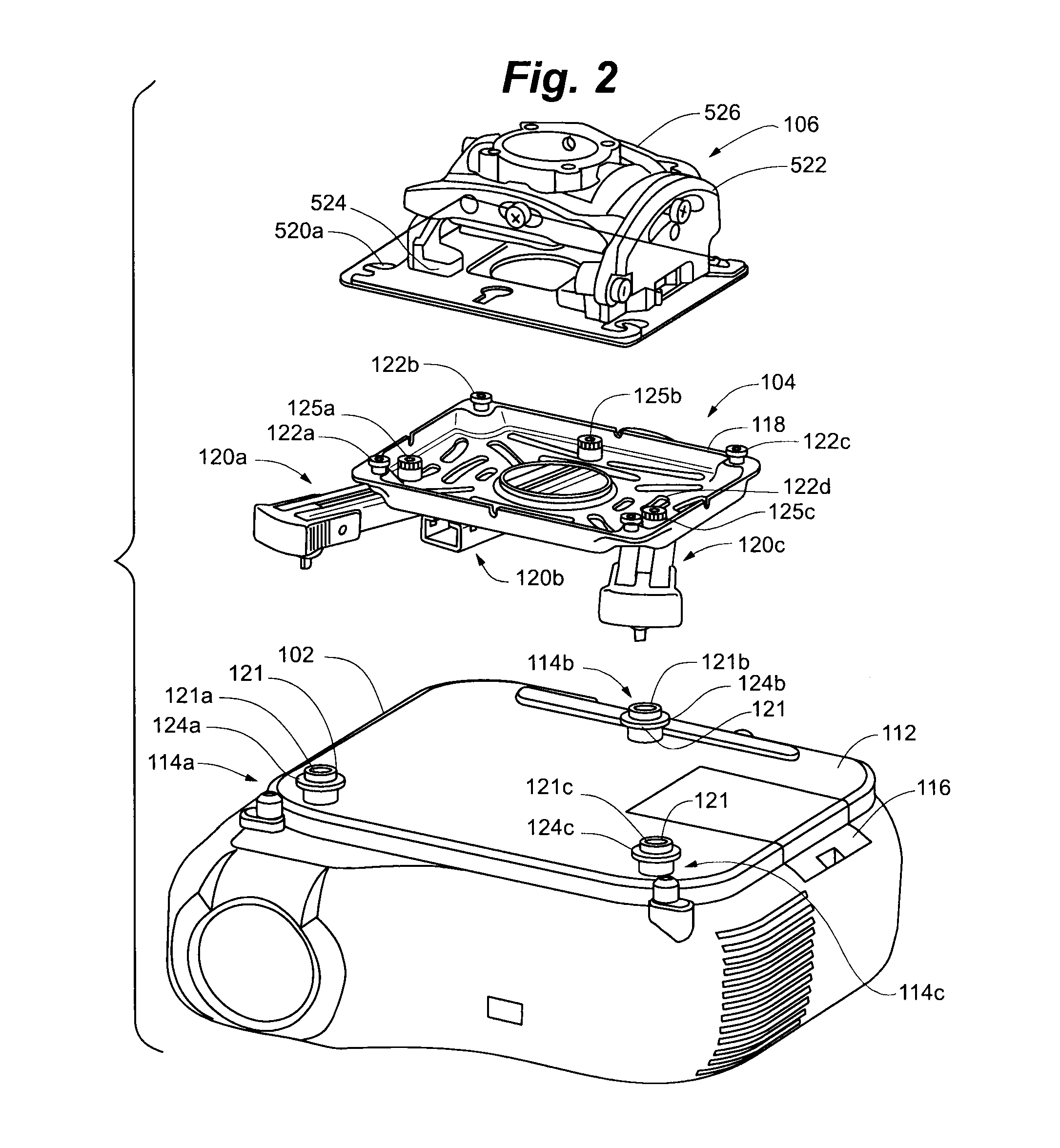
Figure 3
Abstract
Description
RELATED APPLICATIONS
[0001] This application claims the benefit of U.S. Provisional Application No. 61 / 060,968, filed Jun. 12, 2008, and entitled UNIVERSAL PROJECTOR INTERFACE WITH SUSTAINABLE ALIGNMENT, said application being hereby fully incorporated herein by reference.FIELD OF THE INVENTION
[0002] The present invention relates generally to mounting devices and more specifically to universal adjustable mounting devices for projectors.BACKGROUND OF THE INVENTION
[0003] Multi-media presentations performed with video projection equipment have become very common for business and entertainment purposes. Often, the video projection equipment is a portable LCD projector that is placed on a table, cart, or stand in the room, with the image projected on a portion of the wall or a portable screen. Such impromptu arrangements, however, have a number of drawbacks. First, a considerable amount of time is often needed to position, aim, and focus the projector in advance of the presentation—time that...
Examples
Embodiment Construction
[0123]The accompanying Figures depict embodiments of the mount of the present invention, and features and components thereof. Any references to front and back, right and left, top and bottom, upper and lower, and horizontal and vertical are intended for convenience of description, not to limit the present invention or its components to any one positional or spacial orientation. Any dimensions specified in the attached Figures and this specification may vary with a potential design and the intended use of an embodiment of the invention without departing from the scope of the invention. Moreover, the Figures may designate, for reference purposes, the relative directions of x-y-z coordinate axes as applied to the invention. Any reference herein to movement in an x-axis direction, a y-axis direction, or a z-axis direction, or to rotation about an x-axis, a y-axis or a z-axis, relates to these coordinate axes. The y-axis is oriented fore-and-aft in relation to the mounted device, the z-a...