
Tool for electrical investigation of a borehole
Patent Information
- Authority / Receiving Office
- US · United States
- Current Assignee / Owner
- Publication Date
- 2010-01-21
Smart Images
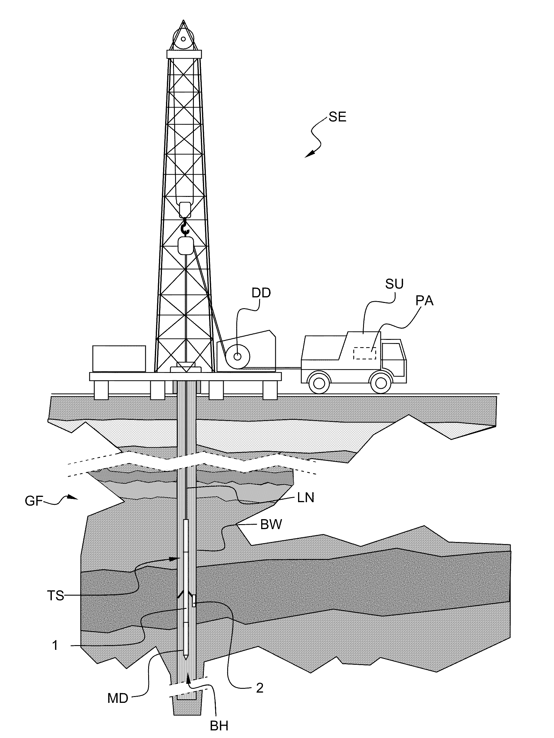
Figure 1 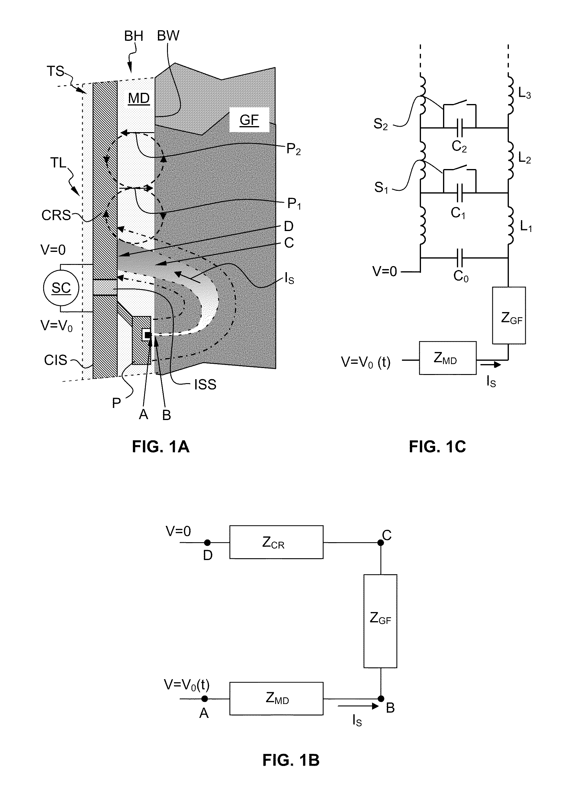
Figure 2 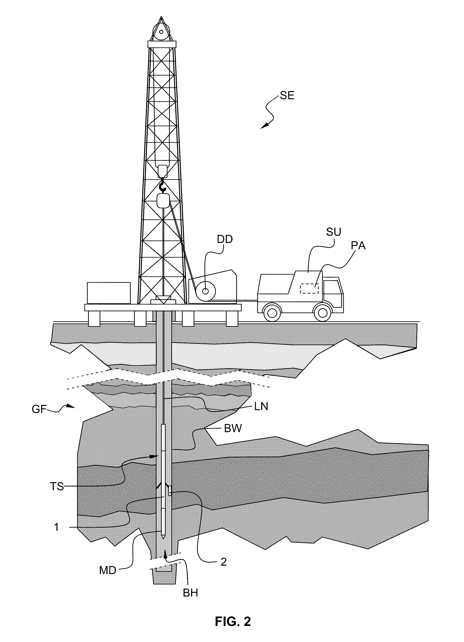
Figure 3
Abstract
Description
FIELD OF THE INVENTION
[0001] The invention relates to a tool used for the electrical investigation of a borehole penetrating geological formations. The tool which is run along the borehole enables micro-electric images of the borehole wall by injecting and measuring survey currents injected into the geological formations. The invention finds a particular application in the oilfield industry.BACKGROUND OF THE INVENTION
[0002] Tools are known, for example from U.S. Pat. No. 4,468,623, U.S. Pat. No. 6,600,321, U.S. Pat. No. 6,714,014 or U.S. Pat. No. 6,809,521 using current injection measurements in order to obtain micro-electric images of a borehole wall, the borehole penetrating geological formations.
[0003] FIG. 1A is a partial cross-section view in a borehole BH showing a part of a typical high-frequency current injection tool TL according to the hereinbefore mentioned prior art. The tool TL is comprised in a string of tool TS. The tool TL comprises a current injection section CIS and a...
Examples
first embodiment
[0058]FIG. 7A schematically illustrates the isolation section ISS2 of the invention. FIG. 7B schematically illustrates the corresponding approximate equivalent circuit model. The isolation section is made of an insulator material. For example, the isolation section may be a coaxial ceramic insulator. The equivalent circuit is a capacitor Cinsu in parallel with a high leakage resistance Rinsu. The impedance of the isolation section is given by:
ZISS=Rinsu1+jωRinsuCinsu≈1jωCinsu
[0059]Typically, the resistance Rinsu is greater than 1 MΩ and the capacitor Cinsu is around 1 nF. At high frequency, the impedance of the isolation section is relatively low due to the large capacitive coupling.
[0060]FIGS. 8-10 schematically illustrate other embodiments of the isolation section. The impedance of the isolation section of these embodiments is increased either by adding a filter-type circuit with an inductive behavior, for example an inductance (FIGS. 8A and 8B), or an active circuit in parallel w...
second embodiment
[0061]FIGS. 8A and 8B schematically illustrate the isolation section according to the invention, and a corresponding approximate equivalent circuit model, respectively. The impedance of a standard tool string insulation section is increased by adding an inductance Linsu in parallel with the capacitor Cinsu. The impedance of the isolation section is given by:
ZISS=ωRinsuLinsujωLinsu+Rinsu-ω2RinsuLinsuCinsu
[0062]As an alternative, the inductance may be tuned for maximum effect at the frequency of operation. In this case, only the leakage resistance limits the impedance, and:
ZISS=RinsuforLinsu=1ω2Cinsu
third embodiment
[0063]FIGS. 9A and 9B schematically illustrate the isolation section according to the invention, and a corresponding approximate equivalent circuit model, respectively. The impedance of a standard tool string insulation section is increased by adding an active circuit in parallel with the capacitor Cinsu. The impedance of the active circuit is for example given by:
-Rinsu1+jωRinsuCinsu,or-1jωCinsu
[0064]In order to compensate for the capacitive coupling, the leakage current through the capacitor Cinsu from the top section A to the bottom section B can be measured and a similar current can be injected from the bottom section B to the top section A. This is realized by an active circuit connected between the top section A and the bottom section B. The active circuit has a response which is the inverse of the response of the capacitor Cinsu in parallel with the resistance Rinsu. Designing active circuit is well known in the art and will not be further described; reference is made to Horo...