
Display apparatus and assembling method thereof
Patent Information
- Authority / Receiving Office
- US · United States
- Current Assignee / Owner
- Publication Date
- 2011-07-21
Smart Images
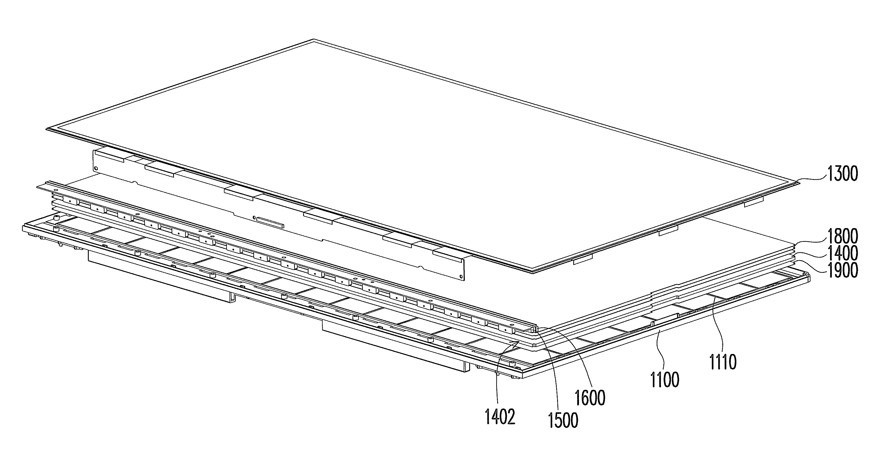
Figure 1 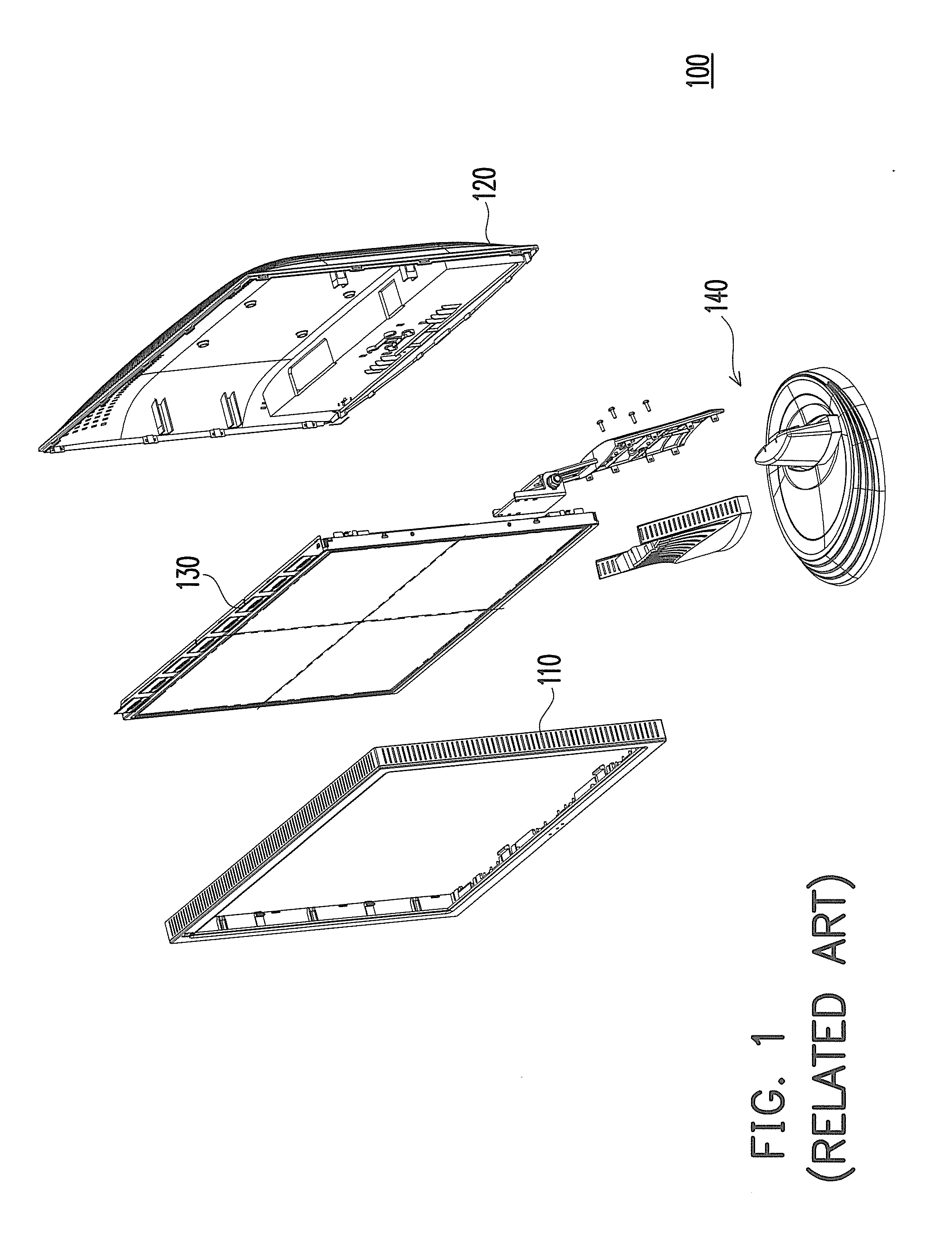
Figure 2 
Figure 3
Abstract
Description
CROSS-REFERENCE TO RELATED APPLICATION
[0001] This application claims the priority benefit of Taiwan application serial no. 99101110, filed on Jan. 15, 2010. The entirety of the above-mentioned patent application is hereby incorporated by reference herein and made a part of specification.BACKGROUND
[0002] 1. Field of the Invention
[0003] The present invention relates to a display apparatus and an assembling method thereof, and more particularly to a light and compact display apparatus and an assembling method thereof.
[0004] 2. Description of Related Art
[0005] With the progress in technologies, image devices have become indispensable in people's daily lives. Flat panel displays (FPD) have such superior characteristics such as light and compact, and low power consumption, that FPDs have gradually replaced conventional cathode ray tube (CRT) displays in recent years.
[0006] FIG. 1 is an explosive view diagram of a conventional liquid crystal display apparatus. Referring to FIG. 1, a conventional...
Examples
Embodiment Construction
[0036]FIG. 4 is an explosive view diagram of a liquid crystal display apparatus according to an exemplary embodiment of the invention. FIG. 5 is a partial, cross-sectional view diagram of the liquid crystal display apparatus in FIG. 4. Referring to FIGS. 4 and 5, the display apparatus 1000 of this exemplary embodiment includes a back cover 1100, a front frame 1200 (this device is omitted in FIG. 4), a display panel 1300, a light guide plate 1400, at least one first metal bracket 1500 and a light emitting device 1600. The front frame 1200 is secured to the back cover 1100, and together they form an accommodating space S10. The display panel 1300 is disposed in the accommodating space S10. The light guide plate 1400 is disposed in the accommodating space S10, between the back cover 1100 and the display panel 1300. In other words, the display panel 1300 and the light guide plate 1400 are sandwiched and secured by the front frame 1200 and the back cover 1100.
[0037]The light guide plate ...