
Optical imaging system with catoptric objective; broadband objective with mirror; and refractive lenses and broadband optical imaging system having two or more imaging paths
an optical imaging system and optical imaging technology, applied in the field of imaging optics, can solve the problems of limited availability of manufacturable anti-reflective (ar) coating materials effective over the spectrum from sub-200 nm to above 400 nm wavelength, and the risk of contamination deposition onto the wafer and/or diffusion, etc., to achieve improved manufacturability, low central obscuration, and high numerical aperture
Patent Information
- Authority / Receiving Office
- US · United States
- Patent Type
- Applications(United States)
- Current Assignee / Owner
- Publication Date
- 2011-10-06
Smart Images
Figure 1 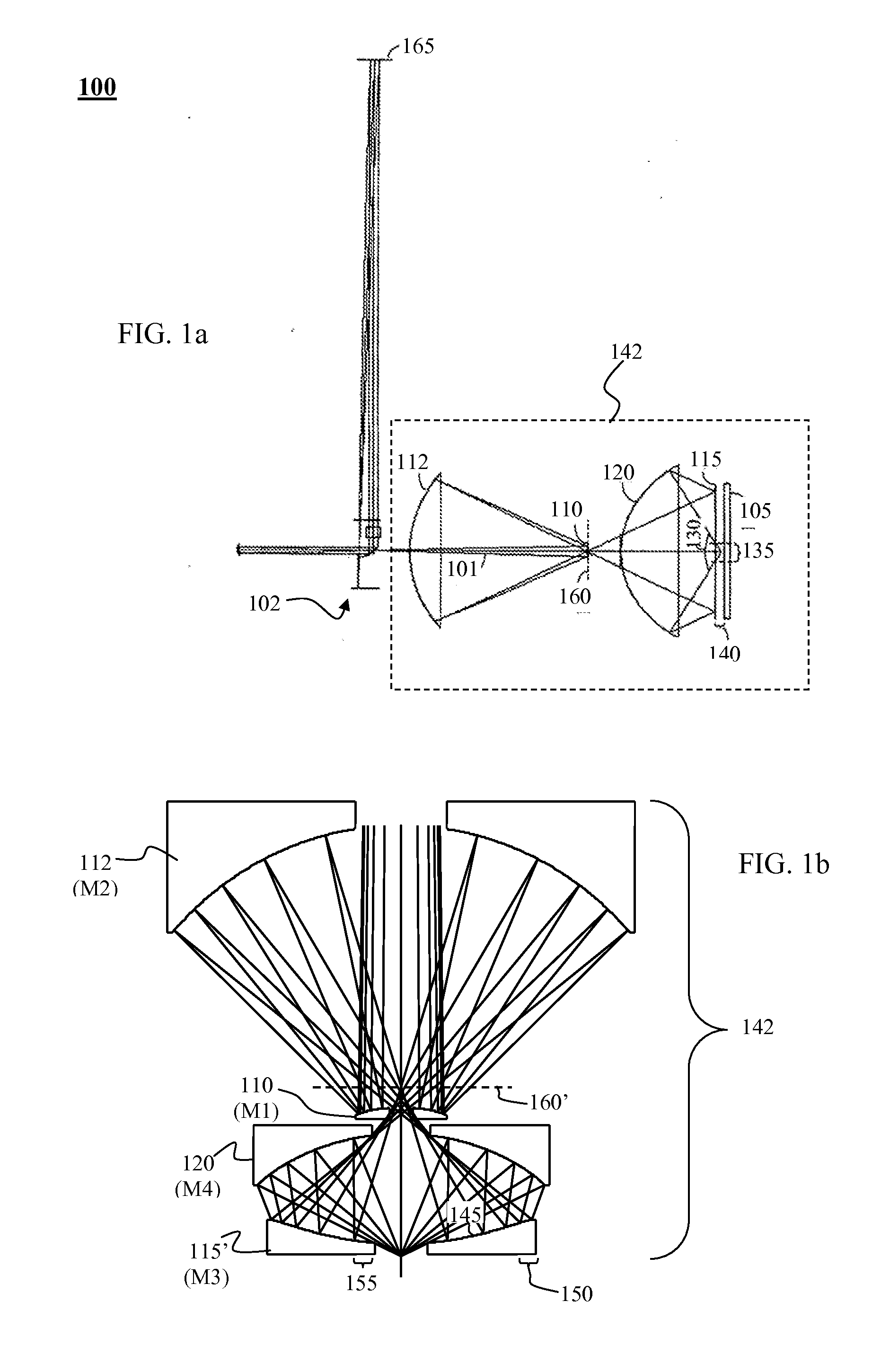
Figure 2 
Figure 3
Abstract
Description
CLAIM OF PRIORITY
[0001] This application claims the priority benefit of U.S. Provisional Patent Application No. 60 / 997,306, filed Oct. 2, 2007, the entire disclosures of which are incorporated by reference herein. This application also claims the priority benefit of U.S. Provisional Patent Application No. 61 / 000,254, filed Oct. 24, 2007, the entire disclosures of which are incorporated by reference herein.
[0002] This application claims the priority benefit of International Patent Application No. PCT / US2008 / 078493, which was filed on Oct. 1, 2008, the entire disclosures of which are incorporated herein by reference.FIELD OF THE INVENTION
[0003] This invention relates to imaging optics for sample inspection, and in particular to the use of catoptric objectives, catadioptric objectives, and the use of multiple wavelength bands and / or inspection modes simultaneously.BACKGROUND OF THE INVENTION
[0004] Defect inspection for the DUV range is currently being performed with all-refractive objectiv...
Examples
Embodiment Construction
[0040]FIG. 1a depicts an example of an optical imaging system 100 that uses a 4-mirror objective design based on the one disclosed in US Patent publication 2006 / 0219930. The optical system depicted in FIG. 1a includes a pupil relay portion 102 and an objective portion 142. The objective portion 142 includes mirrors 110 (M1), 112 (M2), 115 (M3) and 120 (M4). An incident light beam 101 from the pupil relay portion 102 impinges first onto mirror 110 (M1), then mirror 112 (M2), then an outermost mirror 115 (M3), then mirror 120 (M4), then onto sample 105. The sample is generally located close to the outermost mirror 115 in a sample inspection system, such as a wafer inspection system or biological specimen inspection system or mask inspection system. The nomenclature as utilized herein may be construed as a definition of the terms denoting the relative positions of the mirrors within the example being illustrated, i.e., the numbering of the mirrors is defined by the order in which the i...