
Clamp structure
Patent Information
- Authority / Receiving Office
- US · United States
- Current Assignee / Owner
- Publication Date
- 2012-08-23
Smart Images
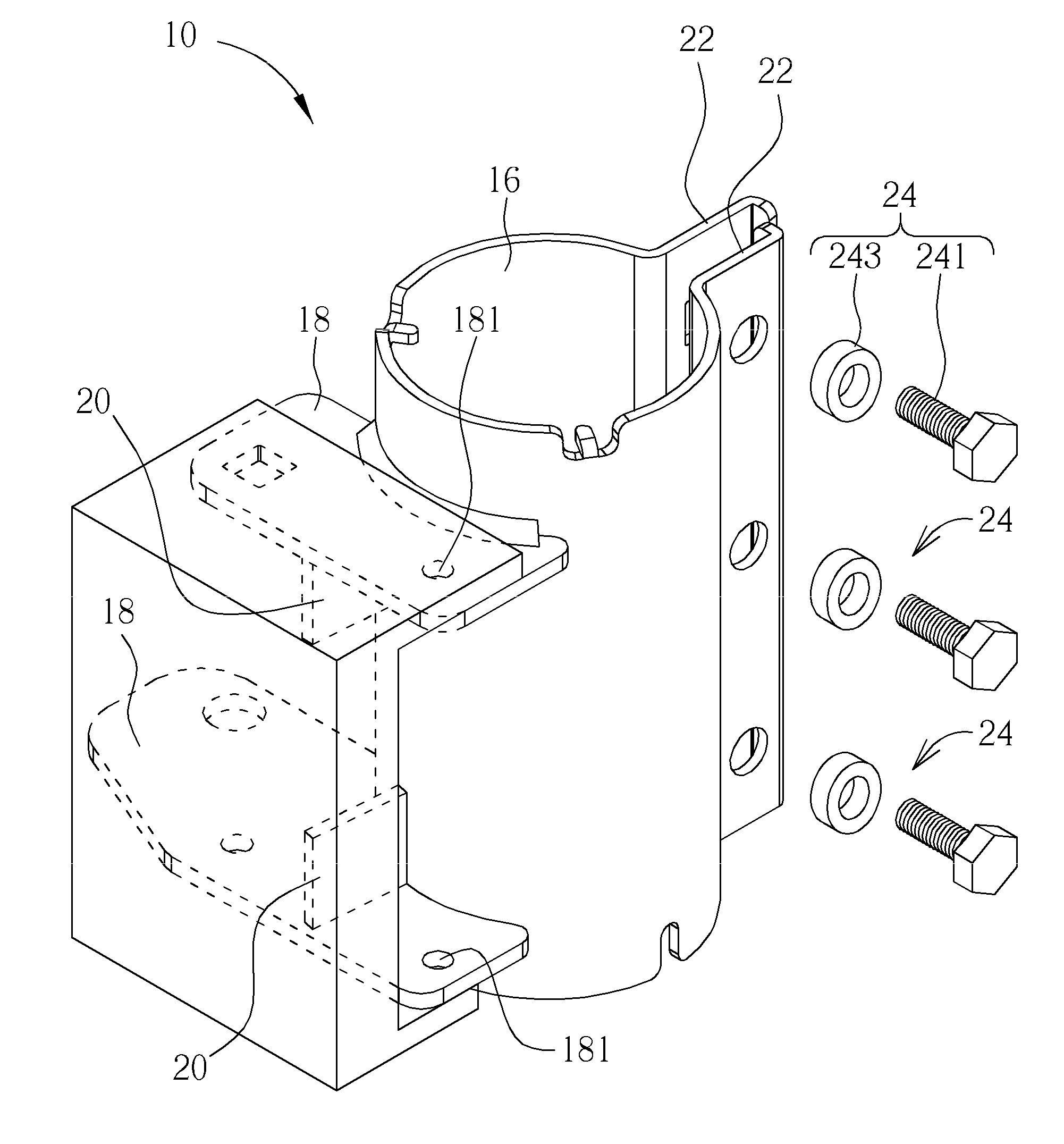
Figure 1 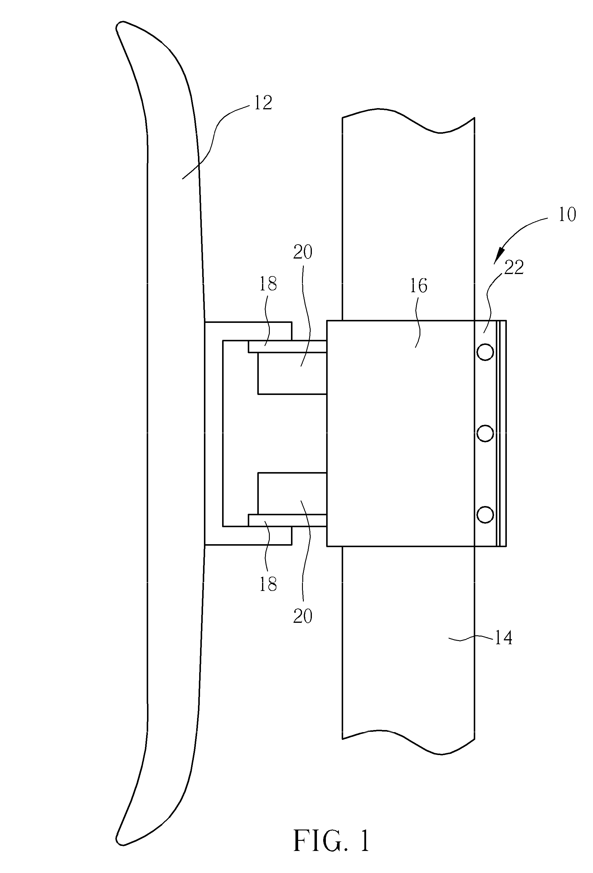
Figure 2 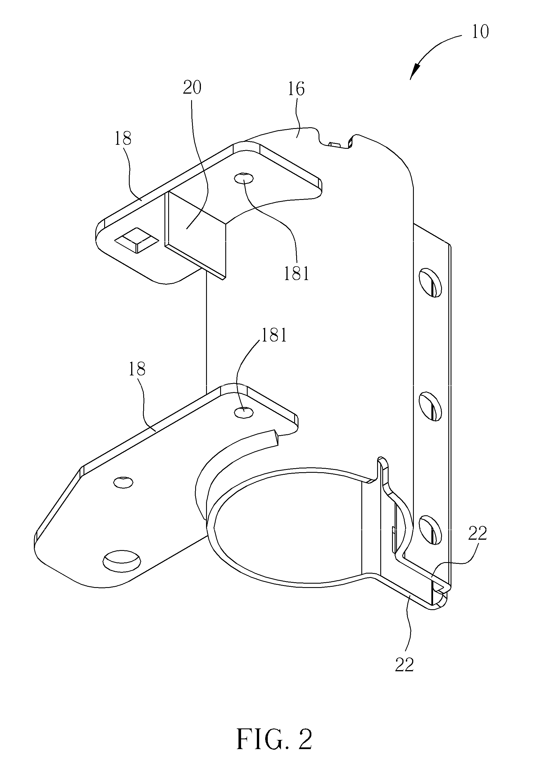
Figure 3
Abstract
Description
BACKGROUND OF THE INVENTION
[0001] 1. Field of the Invention
[0002] The present invention relates to a clamp structure, and more particularly, to a clamp structure for bridging a platform.
[0003] 2. Description of the Prior Art
[0004] For installing an antenna module on a tube, a conventional assembly is disposing the antenna module on a clamp structure, and locking the clamp structure on the tube. A conventional clamp structure includes an annular clamping component for clamping the annular tube, and a bridging component disposed on the annular clamping component. The antenna module is installed on the bridging component of the clamp structure. The conventional clamp structure connects the bridging component to the lateral surface of the annular clamping component as a planar direction of the bridging component is parallel to an axial direction of the annular clamping component. Therefore, the antenna module can pivot relative to the annular clamping component along a direction perpendicul...
Examples
Embodiment Construction
[0018]Please refer to FIG. 1. FIG. 1 is a diagram of a clamp structure 10 and corresponding components according to an embodiment of the present invention. The clamp structure 10 can pivot to an antenna module 12 and sheathe on a tube 14, so that an angle between the antenna module 12 and the tube 14 can be adjusted via the clamp structure 10.
[0019]Please refer to FIG. 2 and FIG. 3. FIG. 2 and FIG. 3 are diagrams of the clamp structure 10 in different view angles according to the embodiment of the present invention. The clamp structure 10 includes a clamping component 16 for clamping the tube 14. The tube 14 can be an annular tube, and the clamping component 16 can be an annular structure correspondingly. The clamp structure 10 further includes at least one bridging component 18 connected to a lateral surface of the clamping component 16 by mechanical treatment, such as a soldering manner or an integrally-formed manner. The bridging component 18 can further stretch from the lateral ...