
Construction of pipes
a technology of hollow structure and pipe, applied in the direction of water-setting substance layered product, mechanical equipment, other domestic articles, etc., can solve the problems of less resilience of flexible outer casings and unfavorable construction process of long pipes to form transportation networks, and achieve the effect of enhancing tensile load bearing properties and stress bearing properties
Patent Information
- Authority / Receiving Office
- US · United States
- Current Assignee / Owner
- Publication Date
- 2014-09-18
Smart Images
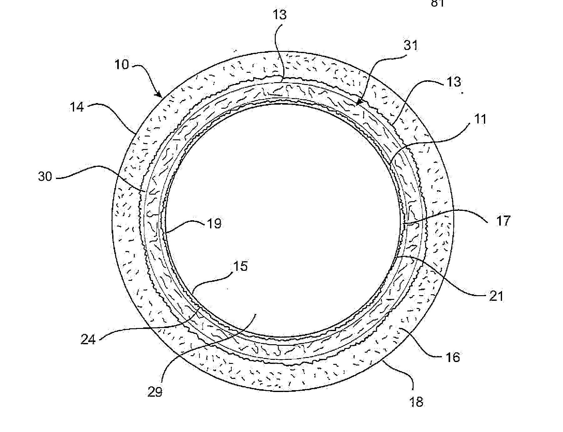
Figure 1 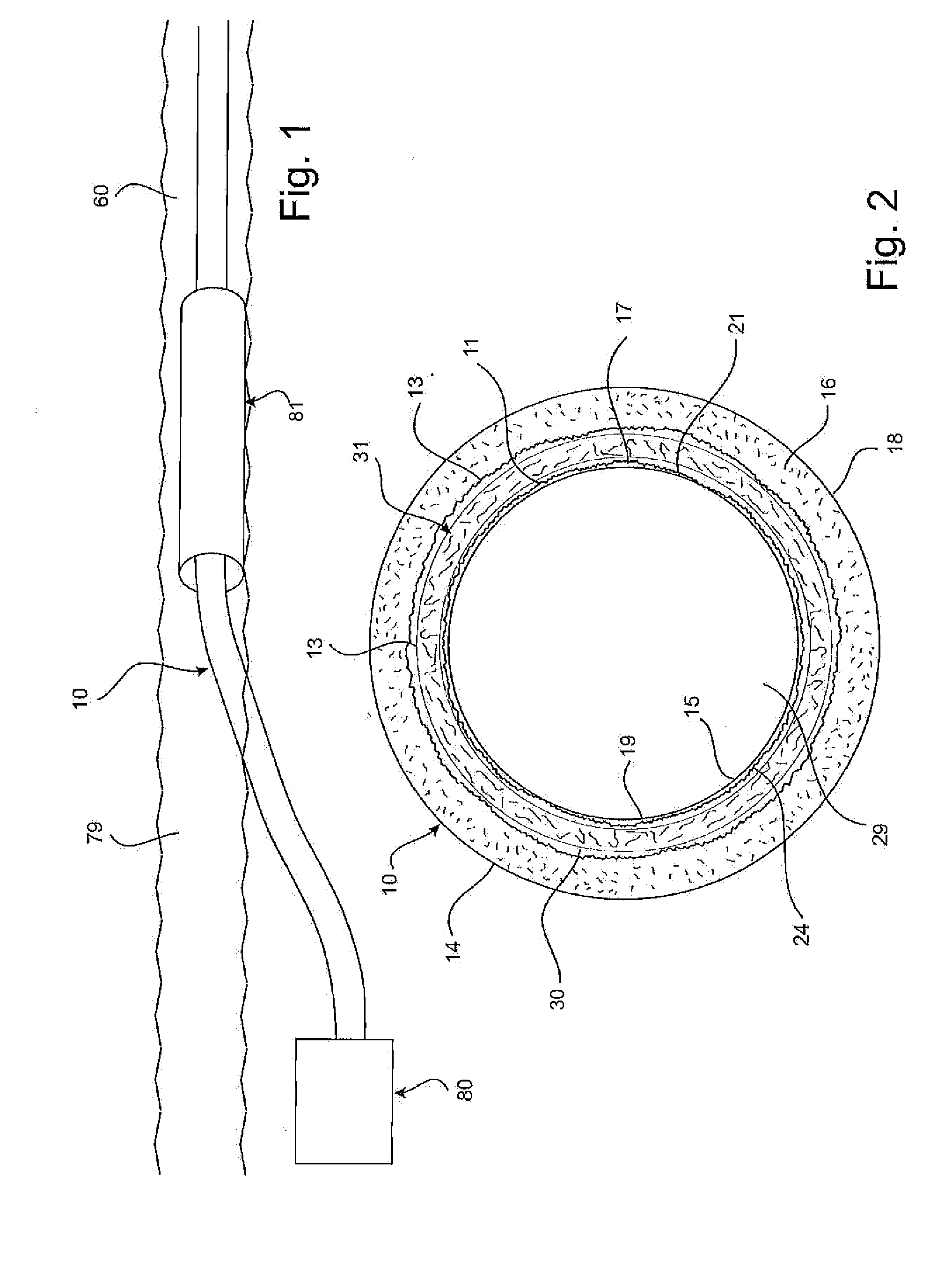
Figure 2 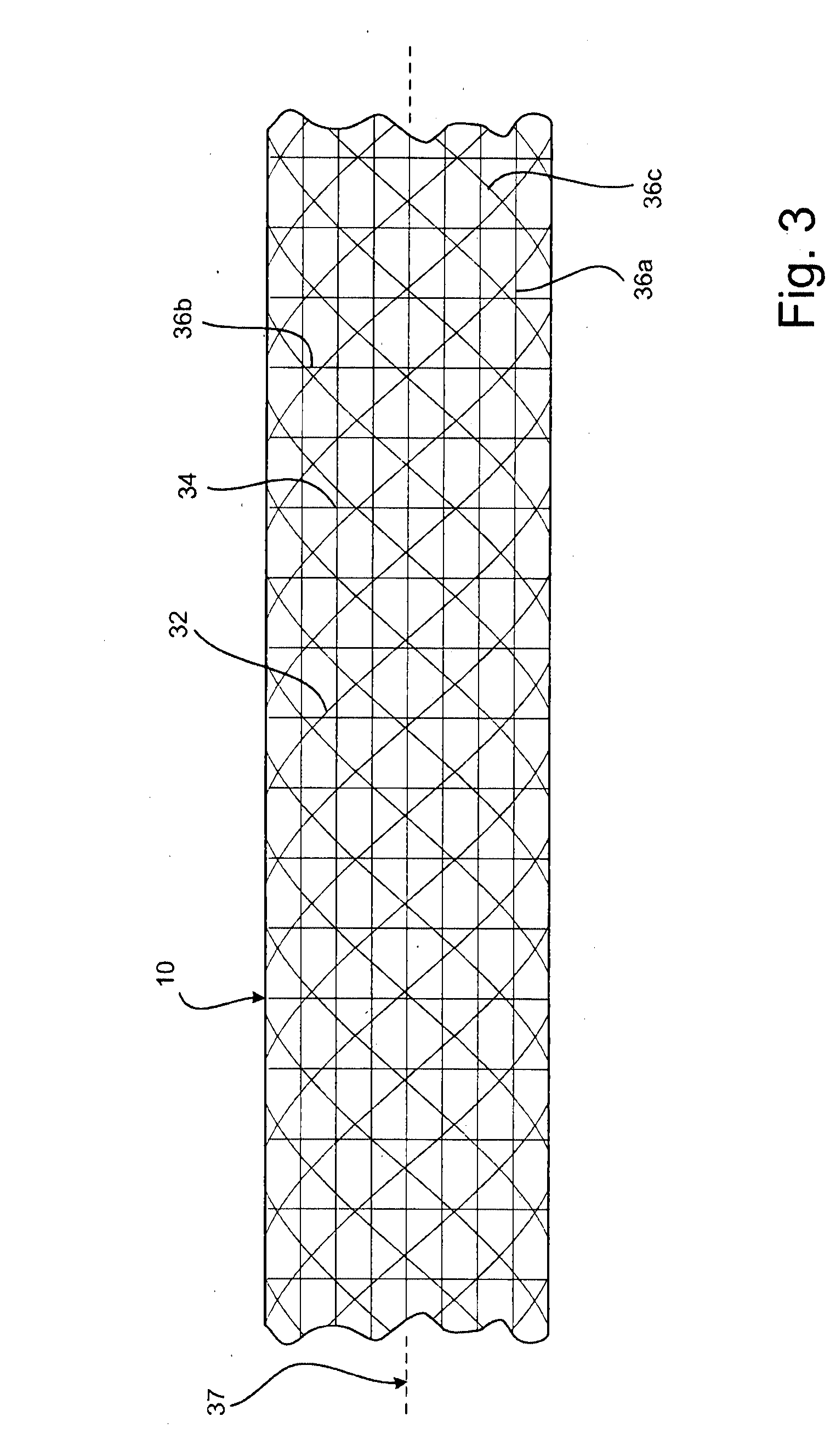
Figure 3
Abstract
Description
CROSS-REFERENCE TO RELATED APPLICATION
[0001] This application claims the benefit under 35 U.S.C. §365(b) of PCT / AU2011 / 001401 to Neil Deryck Bray Graham, filed Oct. 31, 2011 and entitled “CONSTRUCTION OF PIPES”, the entire contents of which is hereby incorporated by reference herein.BACKGROUND
[0002] 1. Field.
[0003] The example embodiments generally relate to elongate hollow structures of composite construction, including in particular tubular structures.
[0004] While the example embodiments have been devised particularly in relation to the construction of tubular structures in the form of pipes, it may also be applicable to the construction of other elongate hollow elements including tubular elements such as ducts and tubes, tubular structural elements such as shafts, beams and columns, and other tubular elements of composite construction.
[0005] 2. Related Art
[0006] The following discussion of the background art is intended to facilitate an understanding of the example embodiments of the p...
Examples
second embodiment
[0188]The pipe assembly line 150 used for the second embodiment employed a flexible outer casing 31 installed around the assembled outer tube structure 100 to contain the resin binder and establish the progressively rising pool 171 of resinous binder for progressively wetting the assembled tube structure 100.
third embodiment
[0189]The pipe assembly line 200 used for the third embodiment also employs an flexible outer casing 31 to contain the resin binder within the assembled outer tube structure 100 and establish the progressively rising pool 171 of resinous binder.
[0190]In this third embodiment, the flexible outer casing 31 is elastic for the purpose of enhancing control of the rate at which the progressively rising pool 171 of resinous binder progressively wets the assembled tube structure 100. If, on the one hand, the pool 171 of resinous binder rises within the annular space 45 too rapidly, it may be that full wet-out of fibres in the assembled tube structure 100 is not achieved. If, on the other hand, the pool 171 of resinous binder rises within the annular space 45 too slowly, it may be that the resinous binder could commence to cure before full wet-out of fibres in the assembled tube structure 100 is achieved.
[0191]The elastic nature of the flexible outer casing 31 functions somewhat as a girdle ...
fifth embodiment
[0217]The installation plant 600 assembles the tubular structure 100 is a manner similar to the previous embodiments. In this embodiment, the installation plant 600 employs apparatus 403 to facilitate a relatively rapid wet-out of the reinforcement 32 and the adjacent resin absorbent layer 17 of the inner liner 21, as described previously in relation to the Additionally, the installation plant 600 has a support structure 605 to support the assembled tubular structure 100 as it is laid into the water 601.
[0218]In this embodiment, the resinous binder used in the construction of the pipe 10 hardens but to a more flexible state (as opposed to hardening to a rigid state as was typically the case with previous embodiments). Specifically, the resinous binder remains flexible after curing in order to provide the pipe 10 with the required flexibility. Resinous binders and other binding agents suitable for such purpose are well known in composite construction techniques and examples of which...