
Catalytic cracking catalyst preparation method
a cracking catalyst and catalytic cracking technology, applied in the field of molecular sieve preparation, can solve the problems of affecting the hydrothermal stability, polluting the environment, affecting the accessibility of active centers, etc., and achieve the effect of reducing the amount of sicl4
Patent Information
- Authority / Receiving Office
- US · United States
- Patent Type
- Applications(United States)
- Current Assignee / Owner
- Publication Date
- 2015-10-15
Smart Images
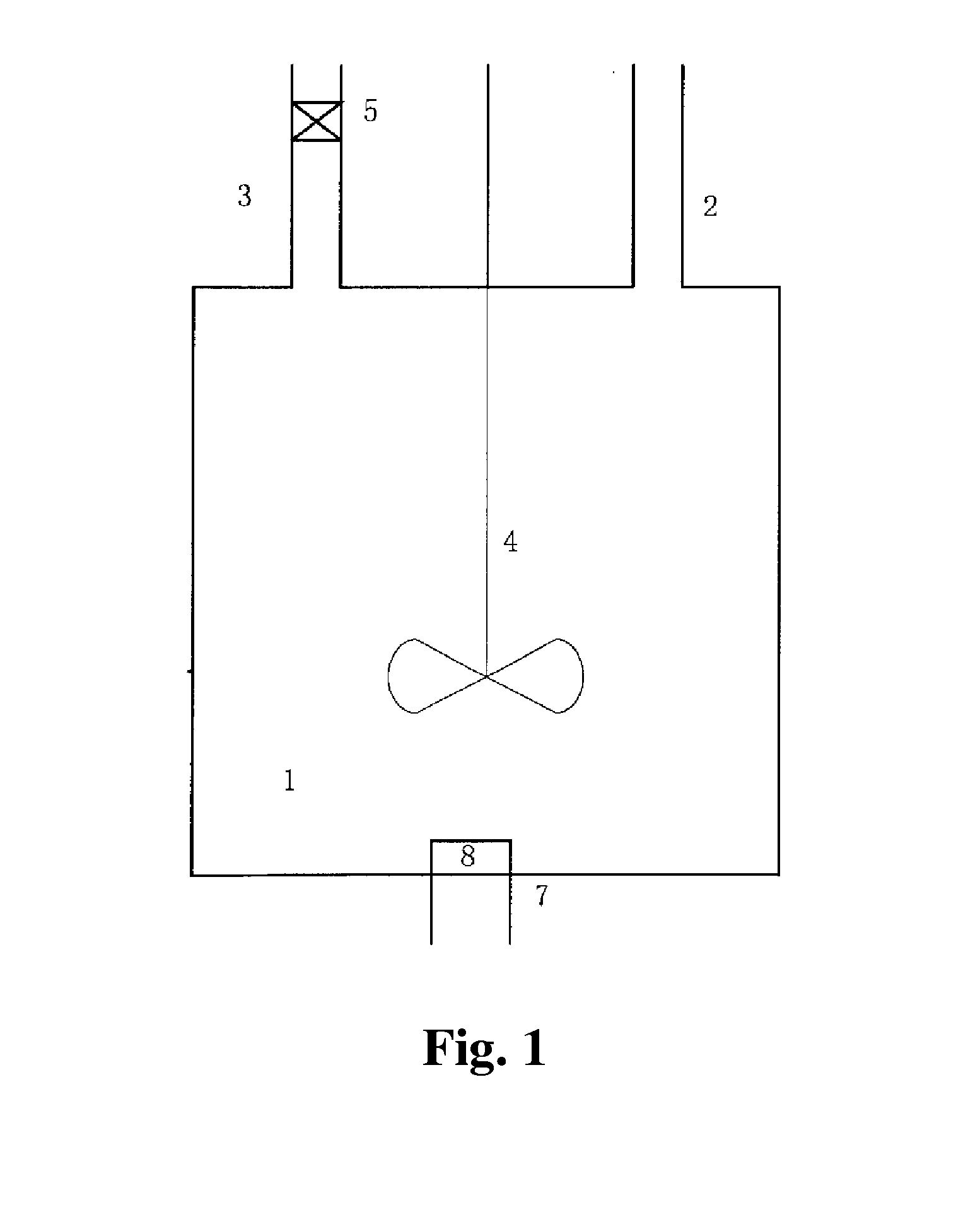
Figure 1 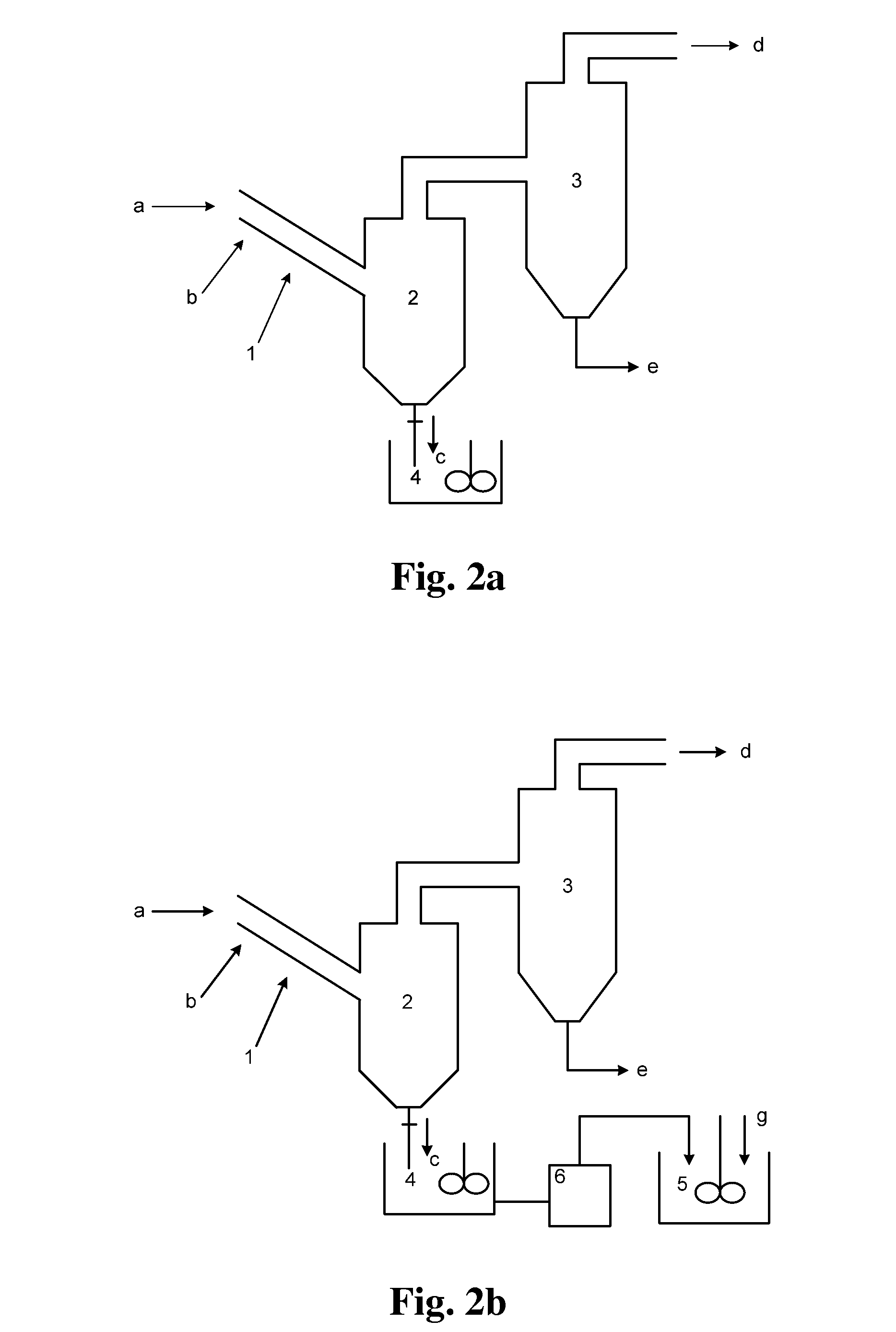
Figure 2 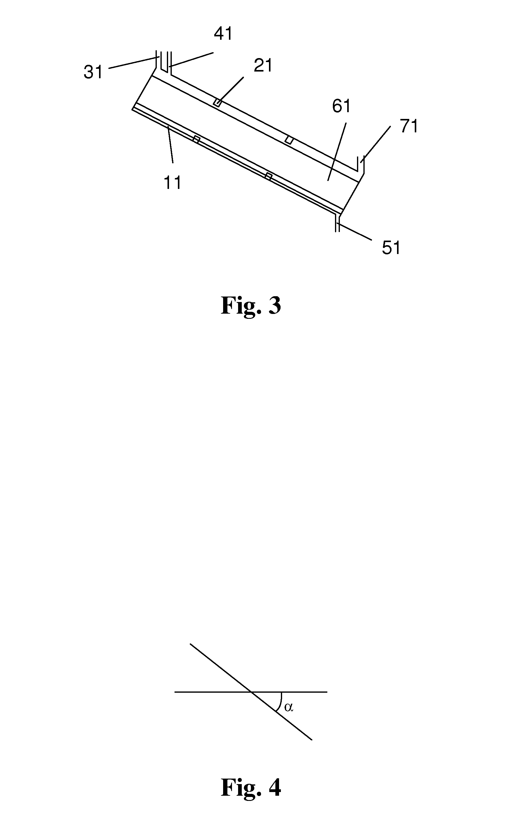
Figure 3
Abstract
Description
TECHNICAL FIELD
[0001] The present invention relates to a process and an apparatus for preparing a molecular sieve. The present invention also relates to a process for preparing a catalytic cracking catalyst.BACKGROUND
[0002] The molecular sieve is a material widely used in the catalytic cracking catalyst, and is also an important component of the catalytic cracking catalyst. The property of the molecular sieve directly affects the reaction performance of the catalytic cracking catalyst. According to different demands, the molecular sieve can be modified in different ways so as to satisfy the use requirement. For example, a molecular sieve with a high silica-alumina ratio is generally considered as being required by the catalytic cracking catalyst.
[0003] In the preparation of a molecular sieve with a high silica-alumina ratio, there are the following processes: dealumination and silicon insertion with ammonium hexafluorosilicate, hydrothermal dealumination and silicon insertion, and gas-...
Examples
example 1
[0195]A molecular sieve gas-phase silicon insertion apparatus was made with a stainless steel of NiCr18Ti in a thickness of 3 mm according to FIG. 2a or 2b or FIG. 8. The upper part of the gas-solid separator 2 was a cylinder with a diameter of 6 meters and a height of 14 meters. The lower part was a cone with an opening. The cone had a cone angle of 45°. A valve was provided at the opening. The outlet was located at a position away from the top of the gas-solid separator by 1 meter. The absorber 3 held an aqueous sodium hydroxide solution (10 mol / L). The absorber 3 and the gas-solid separator 2 were communicated via a conduit, which was inserted into the aqueous sodium hydroxide solution.
[0196]The reactor 1 was a tube reactor, as shown in FIG. 5. The tube body had a total length of 80 meters. The tube body had a diameter of 0.8 meters. The tube body of the reactor was made in an annular shape. The reactor included the upper layer of straight tube and the lower layer of straight tub...
example 2
[0198]A molecular sieve gas-phase silicon insertion apparatus was made with a stainless steel of NiCr18Ti in a thickness of 3 mm according to FIG. 2a or 2b or FIG. 8. The upper part of the gas-solid separator 2 was a cylinder with a diameter of 6 meters and a height of 14 meters. The lower part was a cone with an opening. The cone had a cone angle of 45°. A valve was provided at the opening. The outlet was located at a position away from the top of the gas-solid separator by 1 meter. The absorber 3 held an aqueous sodium hydroxide solution (10 mol / L). The absorber 3 and the gas-solid separator 2 were communicated via a conduit, which was inserted into the aqueous sodium hydroxide solution.
[0199]The tube body of the tube reactor 1 had a length of 60 meters and was a straight tube. The angle between the axis of the tube body of the reactor and the horizontal plane was 45°. The tube body had an inner diameter of 1 meter. As shown in FIG. 3, the molecular sieve was conveyed by gravity. ...
example 3
[0201]A molecular sieve gas-phase silicon insertion apparatus was made with a stainless steel of NiCr18Ti in a thickness of 3 mm according to FIG. 2a or 2b or FIG. 8. The angle between the axis of the tube body of the reactor and the horizontal plane was 55°. The inner diameter of the tube body was 0.5 meter. The upper part of the gas-solid separator 2 was a cylinder with a diameter of 6 meters and a height of 14 meters. The lower part was a cone with an opening. The cone had a cone angle of 45°. A valve was provided at the opening. The outlet was located at a position away from the top of the gas-solid separator by 1 meter. The absorber 3 held an aqueous sodium hydroxide solution (10 mol / L). The absorber 3 and the gas-solid separator 2 were communicated via a conduit, which was inserted into the aqueous sodium hydroxide solution.
[0202]The gas-phase ultra-stabilization reaction apparatus was shown in FIG. 6. The molecular sieve was moved by gravity in the gas-phase ultra-stabilizati...