
Pipe connection for conducting a fluid that is under pressure
Patent Information
- Authority / Receiving Office
- US · United States
- Current Assignee / Owner
- Publication Date
- 2015-10-15
Smart Images
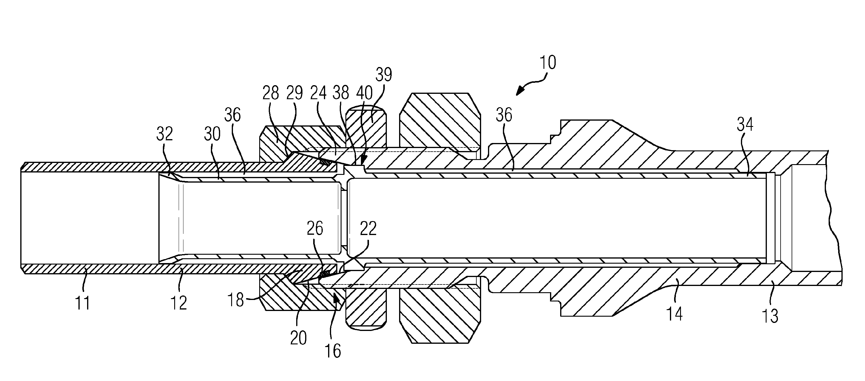
Figure 1 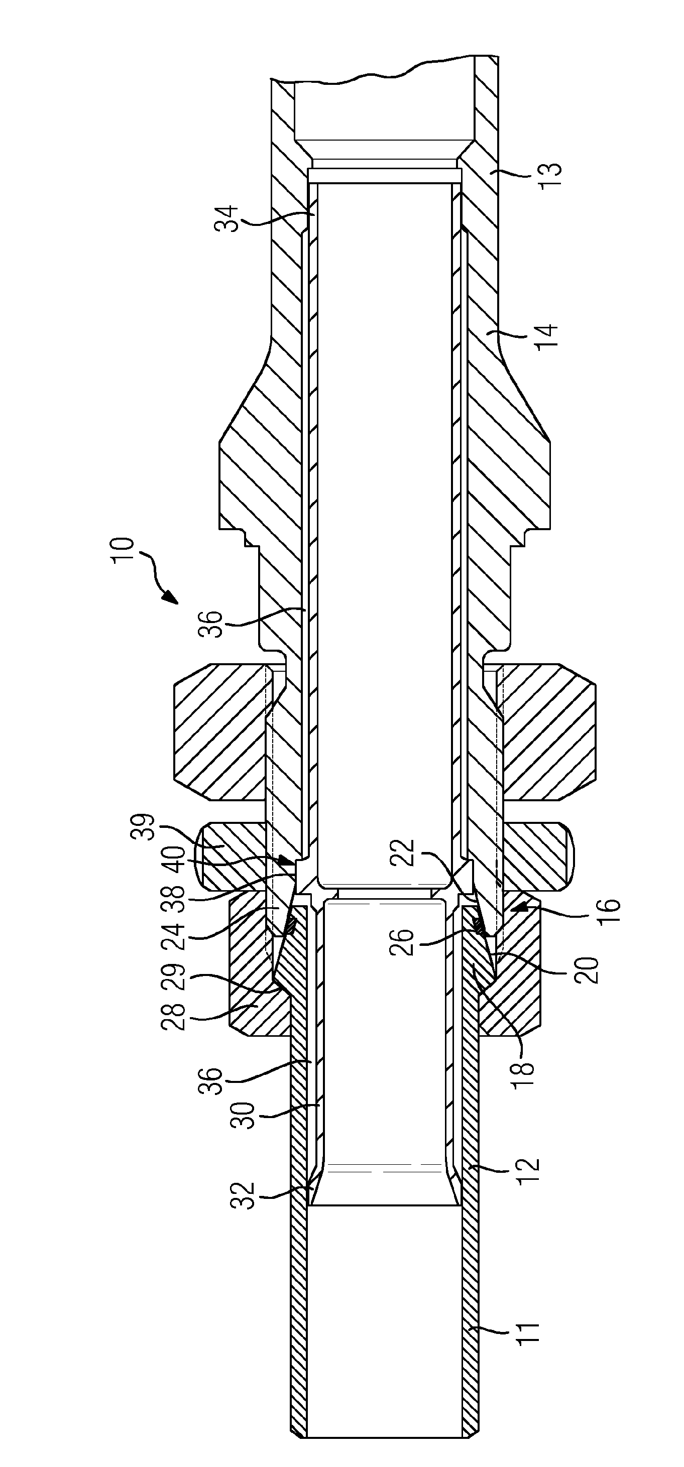
Figure 2
Abstract
Description
CROSS REFERENCE TO RELATED APPLICATIONS
[0001] This application is the US National Stage of International Application No. PCT / EP2013 / 070887 filed Oct. 8, 2013, and claims the benefit thereof. The International Application claims the benefit of German Application No. DE 102012218727.8 filed Oct. 15, 2012. All of the applications are incorporated by reference herein in their entirety.FIELD OF INVENTION
[0002] The invention relates to a pipe connection for conducting a fluid that is under pressure, comprising two tubular connection pieces which are screwed together by means of a union nut, being plugged one into the other in the manner of a cone clamping connection, wherein each connection piece has a conical sealing face which bears in a sealing manner against the other of the two sealing faces.BACKGROUND OF INVENTION
[0003] Pipe connections of the type mentioned in the introduction are very well known from the prior art. For example, DE 1 960 933 U discloses a connection piece, as part of ...
Examples
Embodiment Construction
[0019]The single FIGURE shows, in longitudinal section, a pipe connection 10 for conducting a fluid that is under pressure. In that context, the pipe connection 10 comprises two connection pieces 12, 14 which are connected for a cone clamping connection 16. To that end, the first connection piece 12 has a cone 18 with an outward-oriented conical sealing face 20. The second connection piece 14 has, at an inclination which corresponds to the sealing face 20, an also conical sealing face 22, as part of a cone 24. The cone 24 forms the outer cone and the cone 18 forms the inner cone of the cone clamping connection.
[0020]In the sealing face 20 there is provided an endless circumferential annular groove 26 for receiving graphite as sealant. The two connection pieces 12, 14 are connected to one another with the aid of a union nut 28. Specifically, to that end, the union nut 28 is screwed onto the second connection piece 14, wherein the union nut 28 presses a conical shaft collar 29, as rea...