
Multifunctional engine brake
a multi-functional, engine technology, applied in the field of machine tools, can solve the problems of reducing or even eliminating the valve motion, reducing the speed of the valve seat, and losing all cam motion, so as to reduce the falling off, and effectively slow down and control the valve seat speed
Patent Information
- Authority / Receiving Office
- US · United States
- Patent Type
- Applications(United States)
- Current Assignee / Owner
- Publication Date
- 2019-03-07
Smart Images
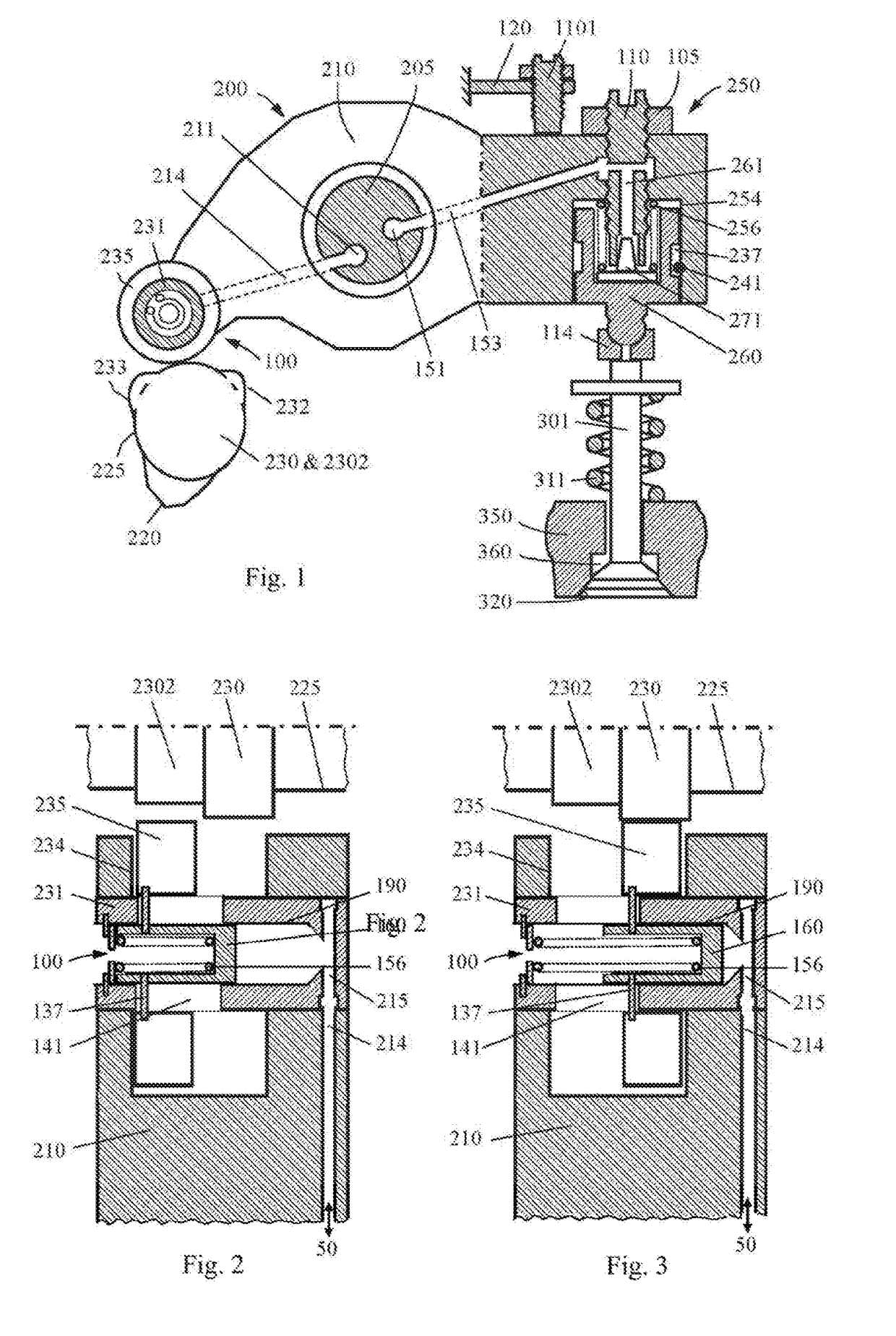
Figure 1 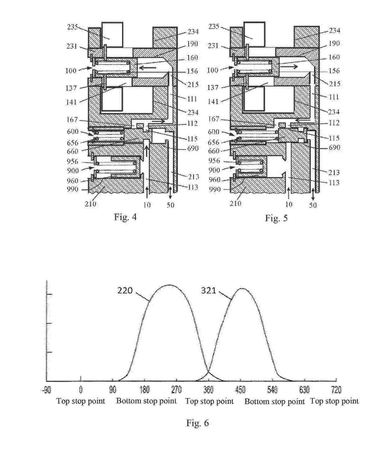
Figure 2 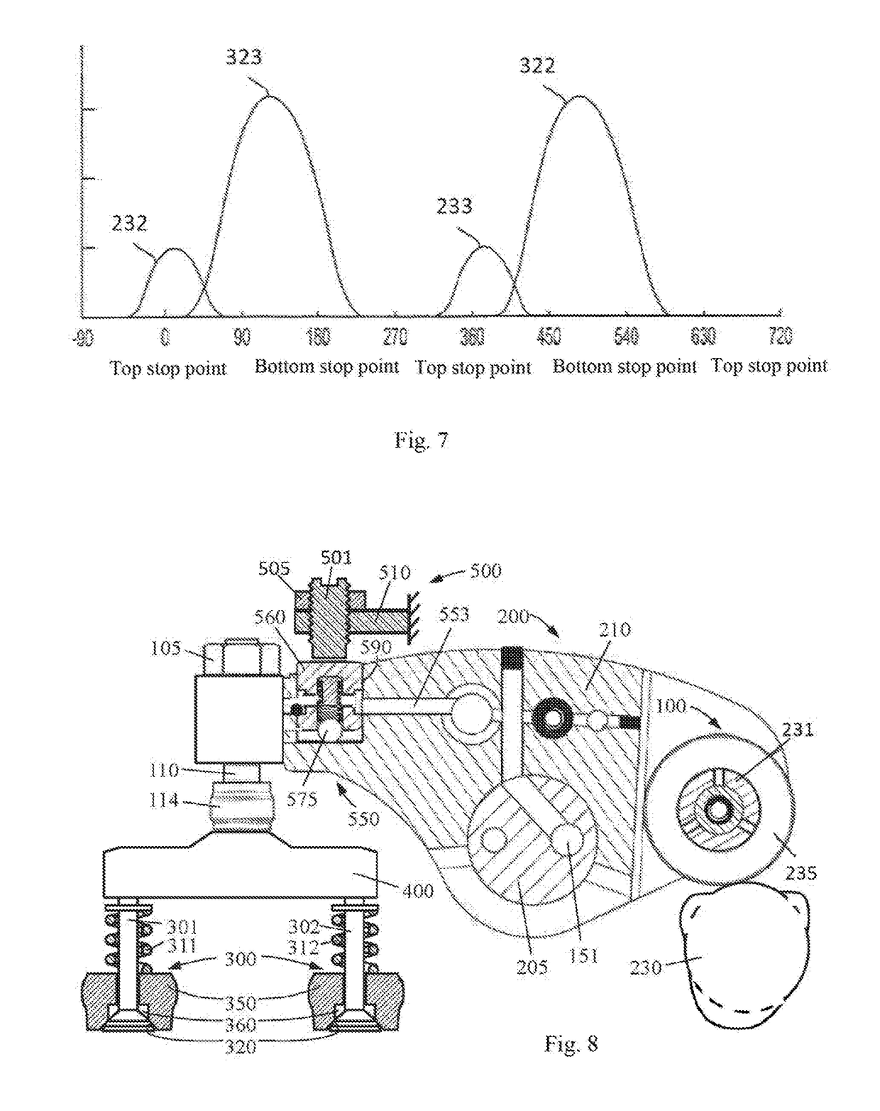
Figure 3
Abstract
Description
TECHNICAL FIELD
[0001] The invention relates to the field of machinery, in particular to engine braking technology, especially a multifunctional engine brake.BACKGROUND ART
[0002] In the prior art, the conventional engine valve drive technology for the engine ignition is well known and its application has a history of more than one hundred years. However, for the additional requirements on engine emissions and engine braking, more and more engines need different valve motions than conventional valve motions, such as exhaust gas recirculation valve motions that reduce emissions, variable valve motions that increase fuel efficiency (including cylinder cutout with valve motions of zero lift) and engine braking valve motions that slow down the vehicle.
[0003] In order to obtain the variable valve motion, for example, from the conventional valve motion to the engine brake valve motion, people often need to add an auxiliary valve drive mechanism (VDM for short) to the conventional VDM, such as ...
Examples
embodiment 1
[0049]FIGS. 1, 2 and 3 are used to describe embodiment 1 of the engine valve motion conversion mechanism in the present invention. FIG. 1 is an illustration (side view) of an engine valve drive device in embodiment 1. The valve actuator 200 (the description herein applies to both the intake valve actuator and the exhaust valve actuator) includes cams (such as a conventional ignition cam 230 and an engine brake cam 2302), a roller 235 and a roller shaft 231. In addition to being able to rotate on the roller shaft 231, the roller 235 can also move axially along the roller shaft 231 (FIGS. 2 and 3). This embodiment shows two different cams 230 and 2302 (for example, the conventional ignition cam 230 and the engine brake cam 2302), which have different profile curves (lift and phase), but they are located on the same camshaft, adjacent to each other and have the same or approximately the same inner base circle 225. The valve actuator 200 also includes a rocker arm (also called a roller ...
embodiment 2
[0056]FIGS. 4 and 5 are used to describe embodiment 2 of the engine valve motion conversion mechanism in the present invention. The main difference between this embodiment and the above embodiment 1 is the oil feeding mode of the axial roller drive mechanism 100. In this embodiment, a directional valve mechanism 600 and an accumulator 900 are added to the rocker arm (roller shaft housing) 210. The directional valve mechanism 600 includes a directional piston 660 and a directional spring 656. One side of the directional piston 660 in the directional piston bore 690 is acted upon by fluid (e.g., oil pressure) and the other side is acted upon by a directional spring 656. The accumulator 900 includes an oil storage piston 960 and an oil storage spring 956. One side of the oil storage piston 960 is acted upon by fluid (e.g., oil pressure) and the other side is acted upon by the oil storage spring 956, so the piston 960 can move between a non-oil storage position (FIG. 4) and a full oil s...
embodiment 3
[0059]FIGS. 8, 9 and 10 are used to describe embodiment 3 of the seating velocity control device in the present invention. FIG. 8 is an illustration (side view) of embodiment 3 of the seating velocity control device in the present invention. The rocker arm 210 is connected to the valve bridge 400 on the end close to the valve 300 through a conventional valve lash adjustment mechanism, and the valve bridge 400 acts on both engine valves 300 (301 and 302) (here, a dual valve engine is shown, but the present invention is also applicable to a single valve engine). The two valves 301 and 302 are biased to the valve seat 320 of the engine block 350 by the valve springs 311 and 312, respectively so as to prevent gas from flowing between the engine cylinder and the gas manifold 360. The conventional valve lash adjusting mechanism includes a valve lash adjusting screw 110, a lock nut 105, and an elephant foot pad 114. From the above description, it can be seen that the valve actuator 200 her...