
Continuous casting method
Patent Information
- Authority / Receiving Office
- US · United States
- Current Assignee / Owner
- Publication Date
- 2019-12-05
Smart Images
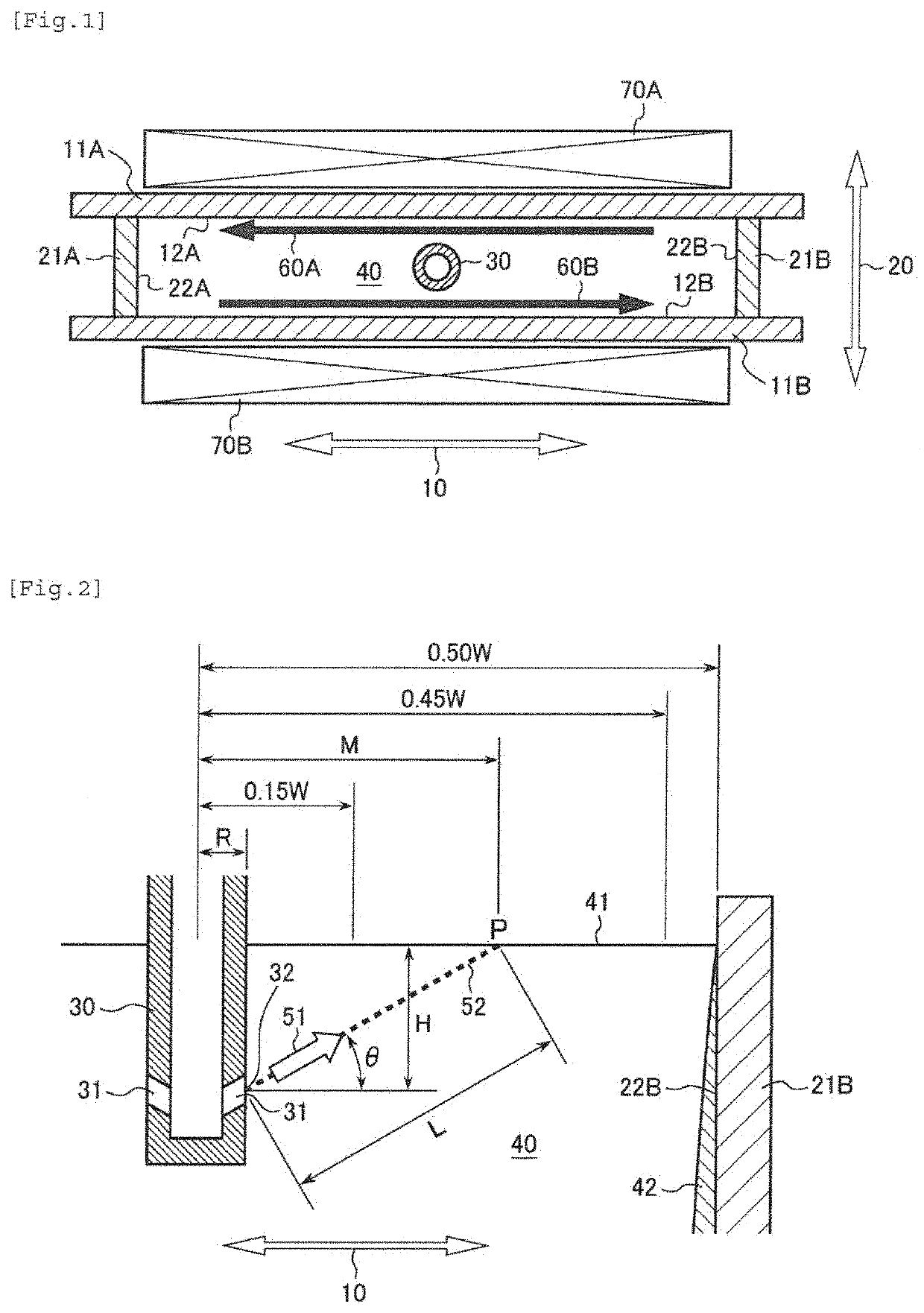
Figure 1 
Figure 2
Abstract
Description
TECHNICAL FIELD
[0001] The present invention relates to a continuous casting method for steel utilizing electro-magnetic stirrer (EMS).BACKGROUND ART
[0002] As a continuous casting method for steel, a method of injecting molten steel into a mold (casting mold) with a submerged nozzle having two discharge ports has been widely employed. The molten steel discharged from the submerged nozzle unavoidably contains bubbles, non-metallic particles, and the like mixed therein. Representative examples of the bubbles include argon gas bubbles. Argon is blown into the molten steel in the process of refining, such as VOD and AOD, used as a seal gas for a tundish, or intentionally added to the molten steel flow channel for preventing clogging of the nozzle, but is substantially not dissolved in the molten steel, and thus tend to mix in the mold as bubbles. The non-metallic particles mainly include a part of such materials as a slag for refining, a deoxidation product formed in the refining process, ...
Examples
example 1
[0051]The ferritic stainless steels having the chemical compositions shown in Table 1 were cast with a continuous casting apparatus to produce cast pieces (slabs).
TABLE 1Chemical composition (% by mass)Steel No.CSiMnNiCrCuMoTiAlNbVNOthers10.0750.5860.4290.1716.13——————0.018—20.0610.4000.2600.1216.01——————0.011—30.0610.6800.4400.1216.280.030.060.0120.005—0.1600.016—40.0060.4920.1890.1511.13——0.2350.060——0.008—50.0060.0900.1000.1517.820.041.040.3520.033—0.0700.012—60.0030.2550.1530.1615.410.060.510.2500.103—0.0540.010B: 0.00170.0060.0400.1600.1717.580.070.910.2680.182—0.0700.013—80.0630.4200.7600.1416.140.060.170.003——0.1200.035—90.0040.0500.0700.1218.140.041.050.2620.246—0.0500.012Zr: 0.10100.0060.0700.1200.1917.650.050.920.2710.267—0.0600.010—110.0100.5400.3300.3319.930.470.05——0.358—0.011—120.0100.4700.3500.2619.040.570.02——0.354—0.013—130.0670.4400.8500.1316.190.070.10———0.1500.026—140.0080.0800.2600.1411.510.060.090.2500.030—0.0400.007—150.0730.6560.3240.1616.12——————0.016—160.00...
example 2
[0062]The influence of the electro-magnetic stirrer on the effect of suppressing the entrainment of foreign matters was investigated by utilizing a part of the ingot charges shown in Table 2A. The continuous casting conditions and the state of defect occurrence of the cold rolled annealed steel sheets are shown in Table 3. The items shown therein the same as in Table 2A. The numeral of the example No. in Table 3 corresponds to the numeral of the example No. in Table 2A, and the examples with the same numeral uses the same ingot charge. Only the electro-magnetic stirrer condition was changed stepwise for the same ingot charge, and coils of cold rolled annealed steel sheets were produced in the same manner as in Example 1 by using the cast pieces (continuous cast slabs) produced under the respective electro-magnetic stirrer conditions, and subjected to the surface inspection. The inspection method was the same as in Example 1. The examples with an electro-magnetic stirrer flow velocit...