
Curved surface processing method for inlet edge of cylindrical blade of centrifugal pump impeller
a centrifugal pump and inlet edge technology, which is applied in the direction of pump components, non-positive displacement fluid engines, liquid fuel engine components, etc., can solve the problems of increased mold making and casting costs, difficult actual manufacturing, etc., and achieves the reduction of the inlet angle at the top of the blade, easy to draft, and improve the adaptability of the inlet edge
Patent Information
- Authority / Receiving Office
- US · United States
- Patent Type
- Applications(United States)
- Current Assignee / Owner
- Publication Date
- 2021-11-25
Smart Images
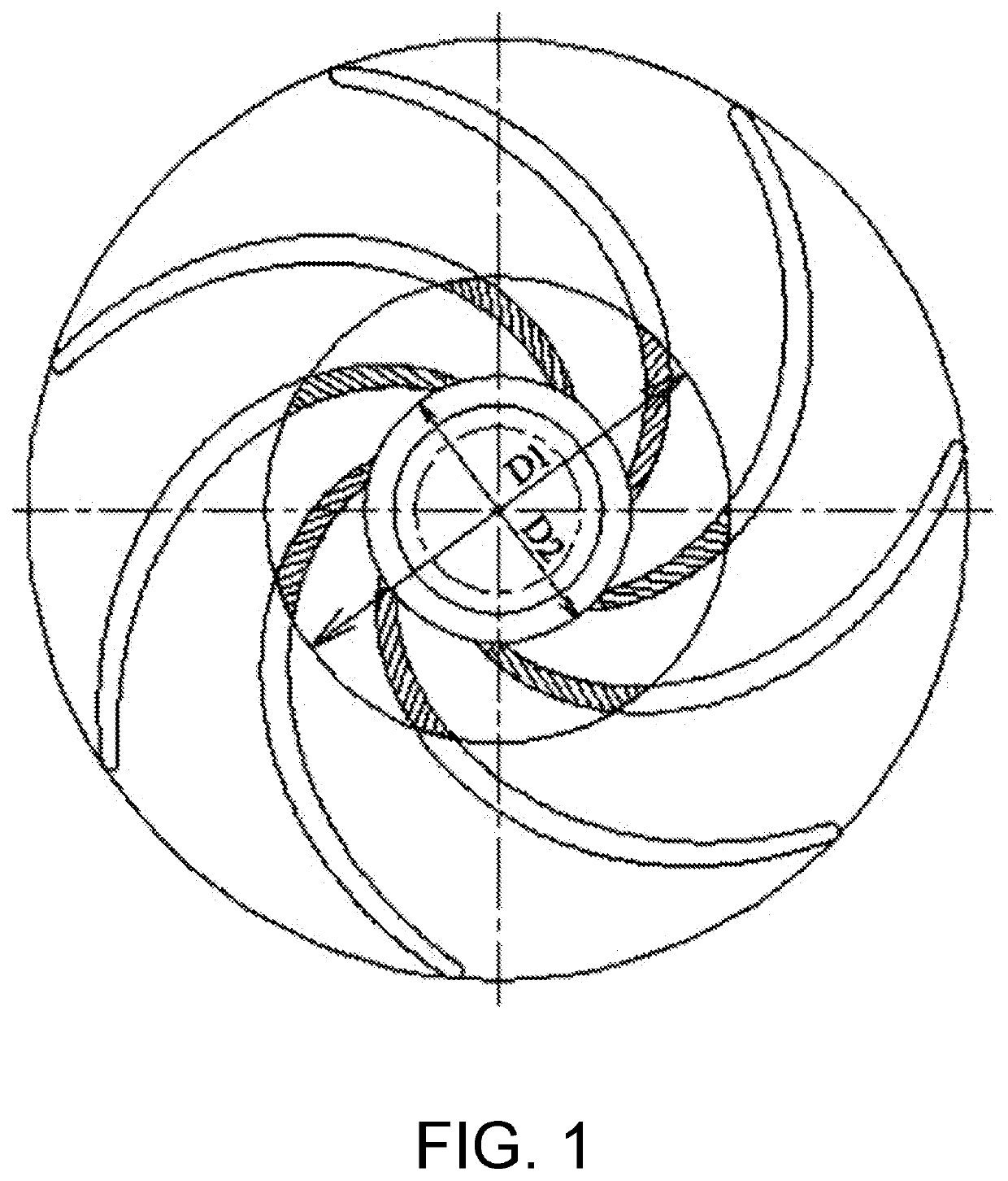
Figure 1 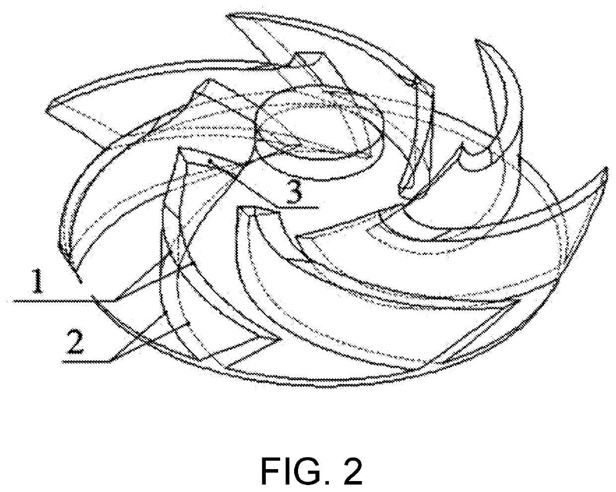
Figure 2 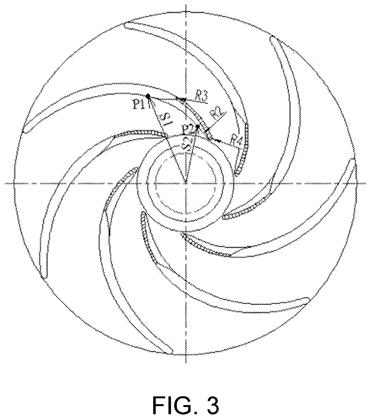
Figure 3
Abstract
Description
BACKGROUNDTechnical Field
[0001] The present invention relates to the technical field of centrifugal pump impellers, and particularly to a curved surface processing method for an inlet edge of a cylindrical blade of a centrifugal pump impeller. Description of Related Art
[0002] In the past, there was little focus on the issue of the design process of a blade inlet in the design of a centrifugal pump with cylindrical blades. In the design of a cylindrical blade, a top curve and a bottom curve of the blade coincide with each other. In the actual design, only one concave side curve and one convex side curve need to be drawn, for example, “or, draw only one middle curve, and specify a blade thickness along the curve” in page 229 of “Handbook of Modern Pump Technology”, First Edition, 1995.
[0003] The journal article “Analysis and Research on Some Cylindrical Blades” in “Drainage and Irrigation Machinery” 2000, studied a method for drawing Archimedean spirals, arc lines, logarithmic spirals, a...
Examples
embodiment 1
[0028
[0029]As shown in FIG. 1, this embodiment provides a curved surface processing method for an inlet edge of a cylindrical blade of a centrifugal pump impeller, and the method includes the following steps.
[0030]Step 1: A center of an impeller with existing cylindrical blades is used as a center to draw s first circle having a first diameter D1 and a second circle having a second diameter D2. The first circle having the first diameter D1 is an improved inlet position at a top of the blade, and the second circle having the second diameter D2 is an improved inlet position at a bottom of the blade.
[0031]Step 2: A first point P1 having a first distance S1 from the center is determined on a concave side curve at the top of the existing cylindrical blade, where the first distance S1=(1.1−1.3)×(D1) / 2. A second point P2 having a second distance S2 from the center is determined on a concave side curve at the bottom of the blade, where the second distance
S2=(1.1−1.3)×(D2) / 2.
[0032]Step 3: Th...