
Rocket motor joint construction including thermal barrier
a technology of thermal barrier and rocket motor, which is applied in the direction of vessel construction, marine propulsion, ornamental textile articles, etc., can solve the problems of affecting the changing the properties and/or dimensions of the casing structure, and not being able to verify the integrity of the seal arrangement. , to achieve the effect of enhancing the sealing effect, enhancing certain functions or properties of the thermal barrier, and facilitating assembly of rocket motor sections
Patent Information
- Authority / Receiving Office
- US · United States
- Patent Type
- Patents(United States)
- Current Assignee / Owner
- Publication Date
- 2002-09-10
- Estimated Expiration
- Not applicable · inactive patent
Smart Images
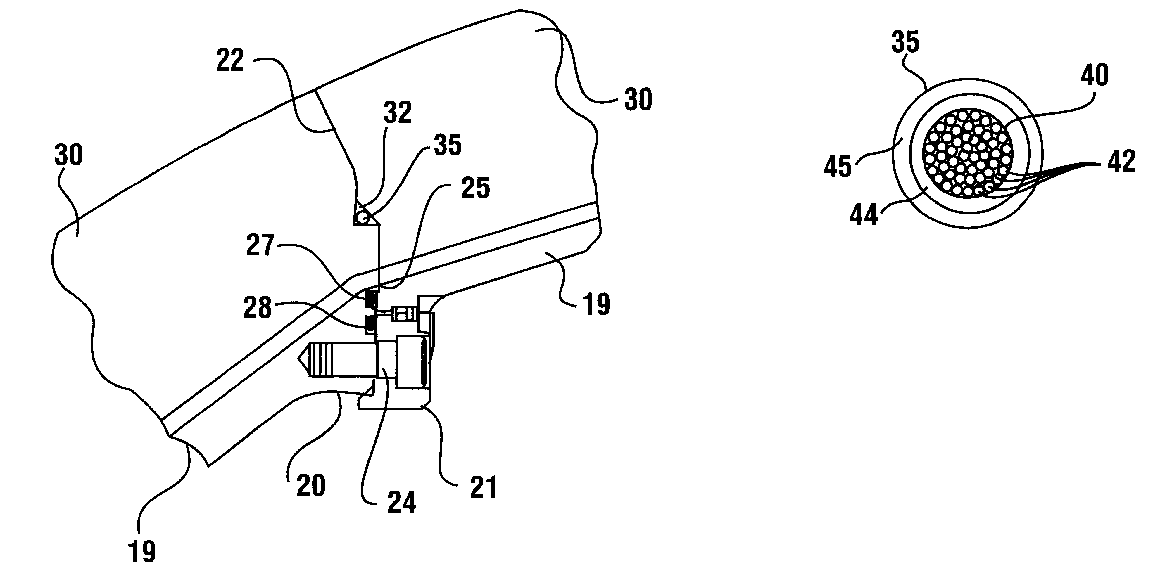
Figure 1 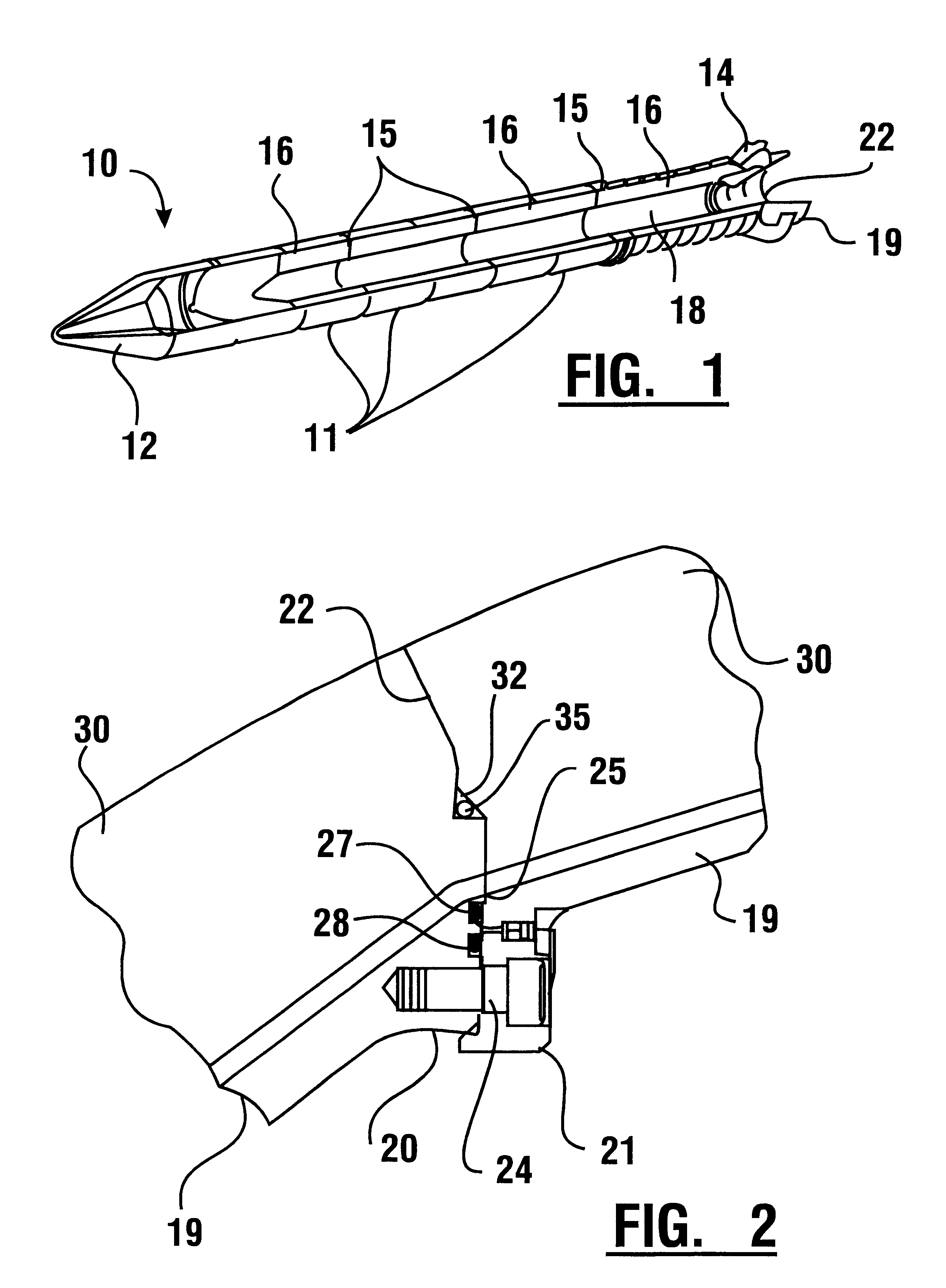
Figure 2 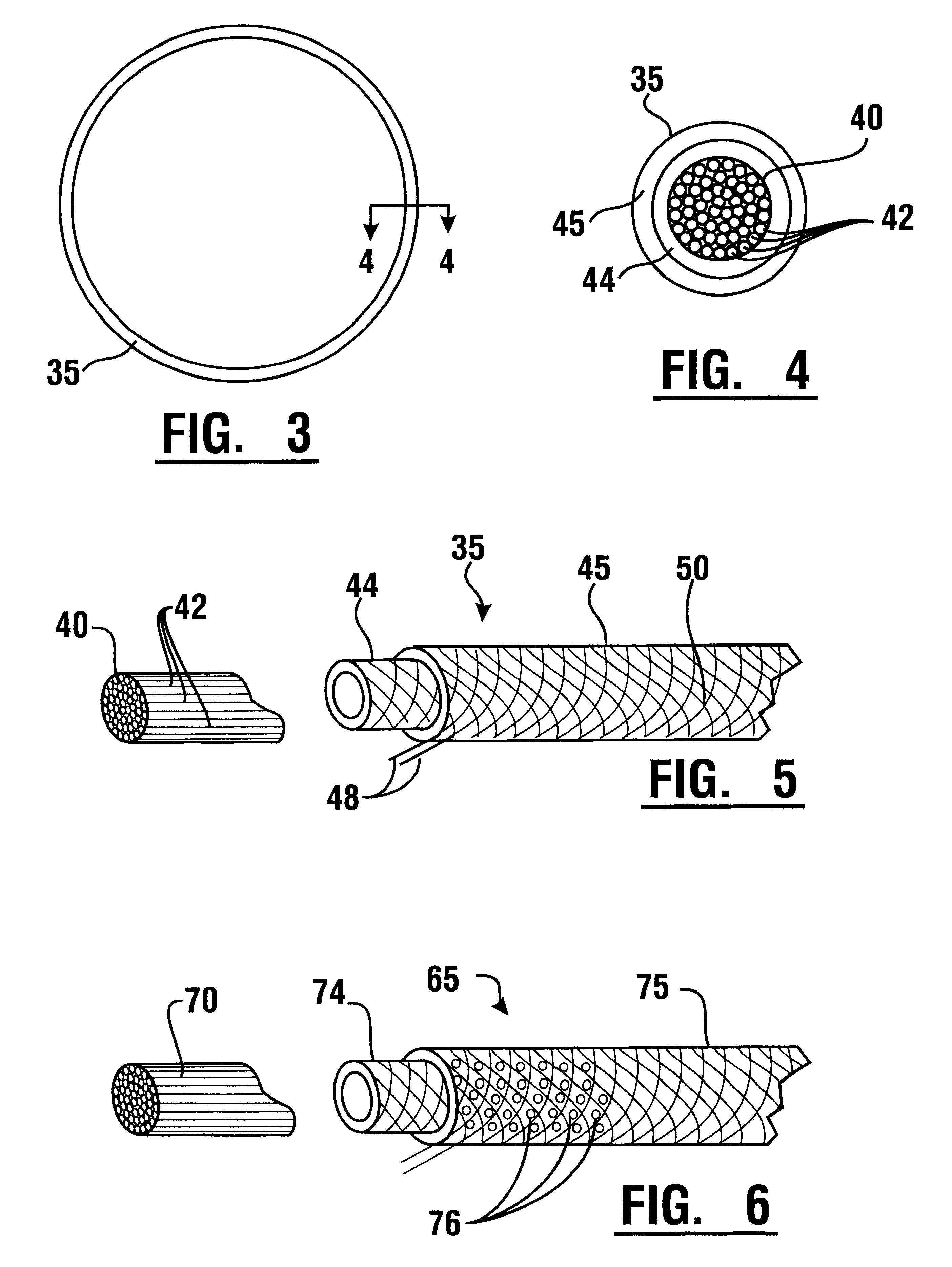
Figure 3
Abstract
Description
This invention relates to sealing devices and more particularly to a rocket motor joint construction which includes a thermal barrier structure in conjunction with elastomeric primary and secondary O-ring seals between casings of a solid rocket motor.Assembly joints of current solid rocket motor cases are generally sealed using high performance, elastomeric O-ring seals. The 5500.degree. F. propulsion gases commonly produced during the relatively short firing interval of the rocket motors are kept a safe distance away from compounds are used to fill insulation gaps leading to the seals to prevent a flowpath of propulsion gases to the seals.Normally, these two stages of protection are enough to prevent a direct flowpath of the 900-psi hot gases from reaching the seals. Occasionally, seals have experienced charring due to parasitic leakage paths that open up in the joint-fill compounds during rocket operation. Inspection during disassembly of Space Shuttle solid rocket motor nozzle jo...
Examples
Embodiment Construction
Referring now to the drawings there is shown in FIG. 1 a solid rocket motor 10 in which the teachings of an exemplary embodiment of the present invention are applied. Rocket motor 10 is segmented and comprised of a plurality of generally cylindrical casings or casing sections 11. A frustum or nose fairing 12 is located at the forward end. A nozzle 14 and thrust vector control system are located at the aft end. The casings 11 are axially aligned and joined to one another through casing joints 15 therebetween. The casings are lined inside with tubular sections of rocket propellant 16, forming a central chamber 18 for enabling axial flow of rocket combustion gases during the rocket burn. Rocket motor nozzle 14 is segmented and comprised of a plurality of generally cylindrical or conical nozzle segments or sections 19.
In FIG. 2 is an enlarged view of a part of a lower casing joint 22 between adjacent nozzle segments 19. The joint 22 extends through mating flanges 20, 21 of forward and a...