
Electromagnetic flow meter for low conductivity fluids
a low conductivity fluid and flow meter technology, applied in the field of electromagnetically driven flow meters, can solve the problems of small reduction, change in measured potential, and inability or undesirable, and achieve the effect of increasing the length of the electrode and reducing the effective electrode impedan
Patent Information
- Authority / Receiving Office
- US · United States
- Patent Type
- Patents(United States)
- Current Assignee / Owner
- Publication Date
- 2006-10-10
- Estimated Expiration
- Not applicable · inactive patent
Smart Images
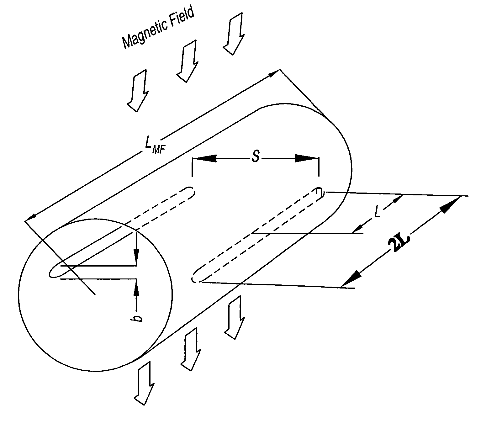
Figure 1 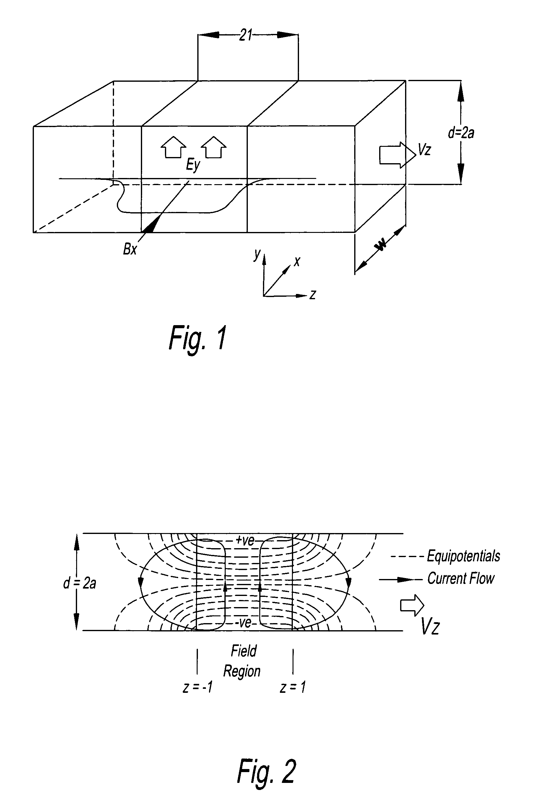
Figure 2 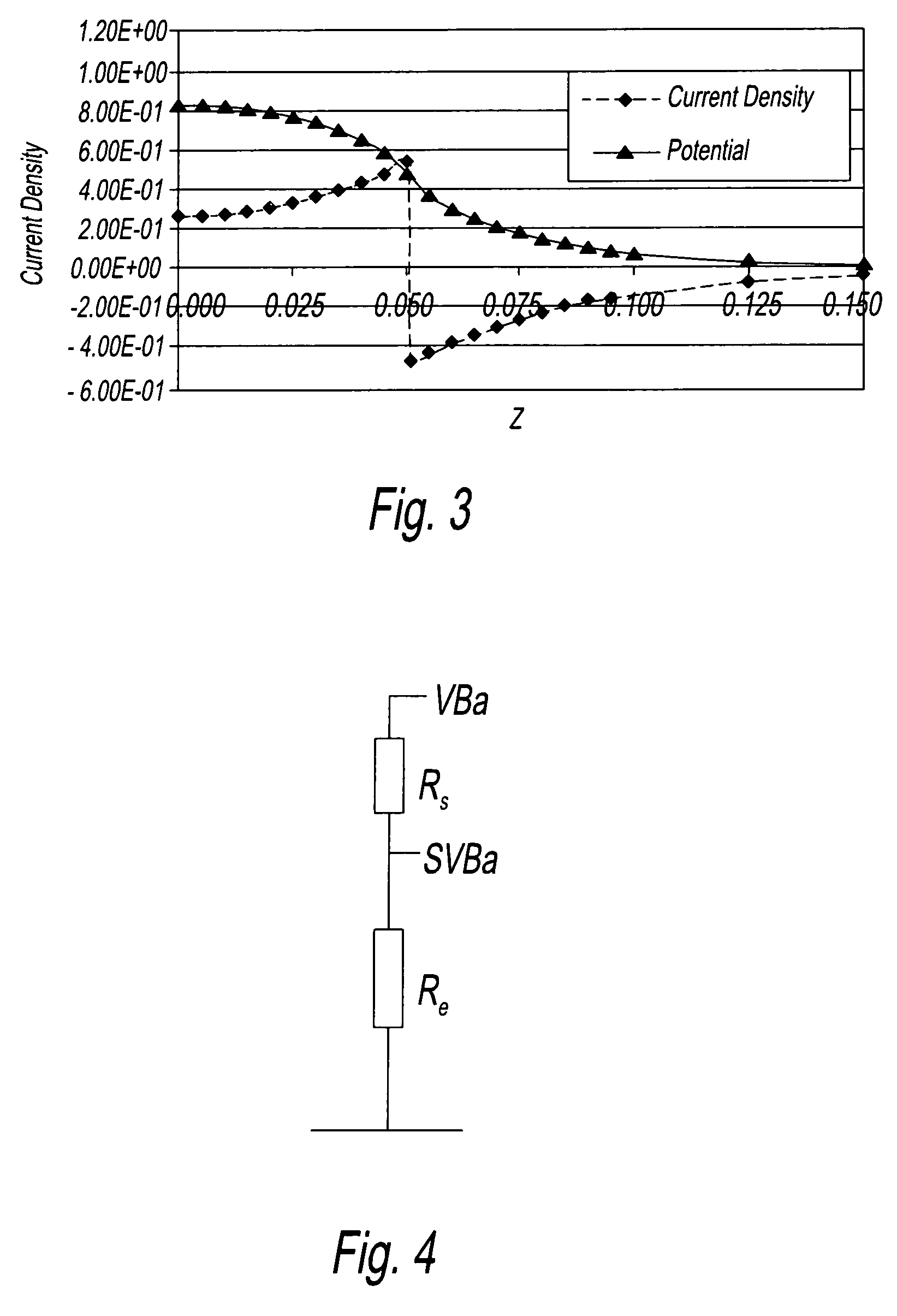
Figure 3
Abstract
Description
BACKGROUND OF THE INVENTION
[0001] 1. Field of the Invention
[0002] The present invention relates to electromagnetic flow meters.
[0003] 2. Description of Related Art
[0004] Electromagnetic flow meters have been used for many years for measuring the flow of a conductive fluid. Electromagnetic flow meters have a number of advantages over mechanical meters as they can be made relatively compact and without moving parts to wear or become damaged by inclusions within the fluid. Electromagnetic flow meters work on the principle that a magnetic field (which may be static or time-varying) induces an EMF across a moving fluid. As a practical matter however, the EMF is typically small and measuring it with practical instruments without undue sensitivity to noise is a concern.
[0005] It conveniently so happens that water-based fluids, which constitute a usefully large proportion of process fluids to be monitored, tend to have a conductivity that can be measured using an electromagnetic flowmeter of con...
Examples
Embodiment Construction
[0048]To assist in understanding the present invention, a theoretical explanation will first be given.
[0049]A magnetic flow meter is in essence a type of M.H.D. (magneto-hydrodynamic) generator. A simple form consists of a duct, lined with an electrically insulating lining through which the fluid to be measured flows, and in operation the fluid is made to pass through a transverse magnetic field within the duct. The moving fluid creates an electric field, E in a direction perpendicular to the motion, and to the magnetic field. The strength of the electric field depends upon the velocity V, and upon the intensity of the field B. Appropriately placed electrodes are connected to electronic apparatus that measures the potential difference between them and converts this into a form that indicates the mean flow through the meter. The details of the electronic apparatus are not germane and many conventional schemes are known which may be used herein.
[0050]FIG. 1 shows the layout of a simpl...