
Press action simulator for aerial cam set up
a technology of aerial cams and simulators, which is applied in the direction of forging presses, forging/pressing/hammering apparatuses, and tools for forming tools. it can solve the problems of inflating the cost of setting up the press, wasting time and time, and unable to adjust the tools on the slide at the trial and error method, etc., and achieves the effect of quick and accurate operation
Patent Information
- Authority / Receiving Office
- US · United States
- Patent Type
- Patents(United States)
- Current Assignee / Owner
- Publication Date
- 2008-03-04
- Estimated Expiration
- Not applicable · inactive patent
Smart Images
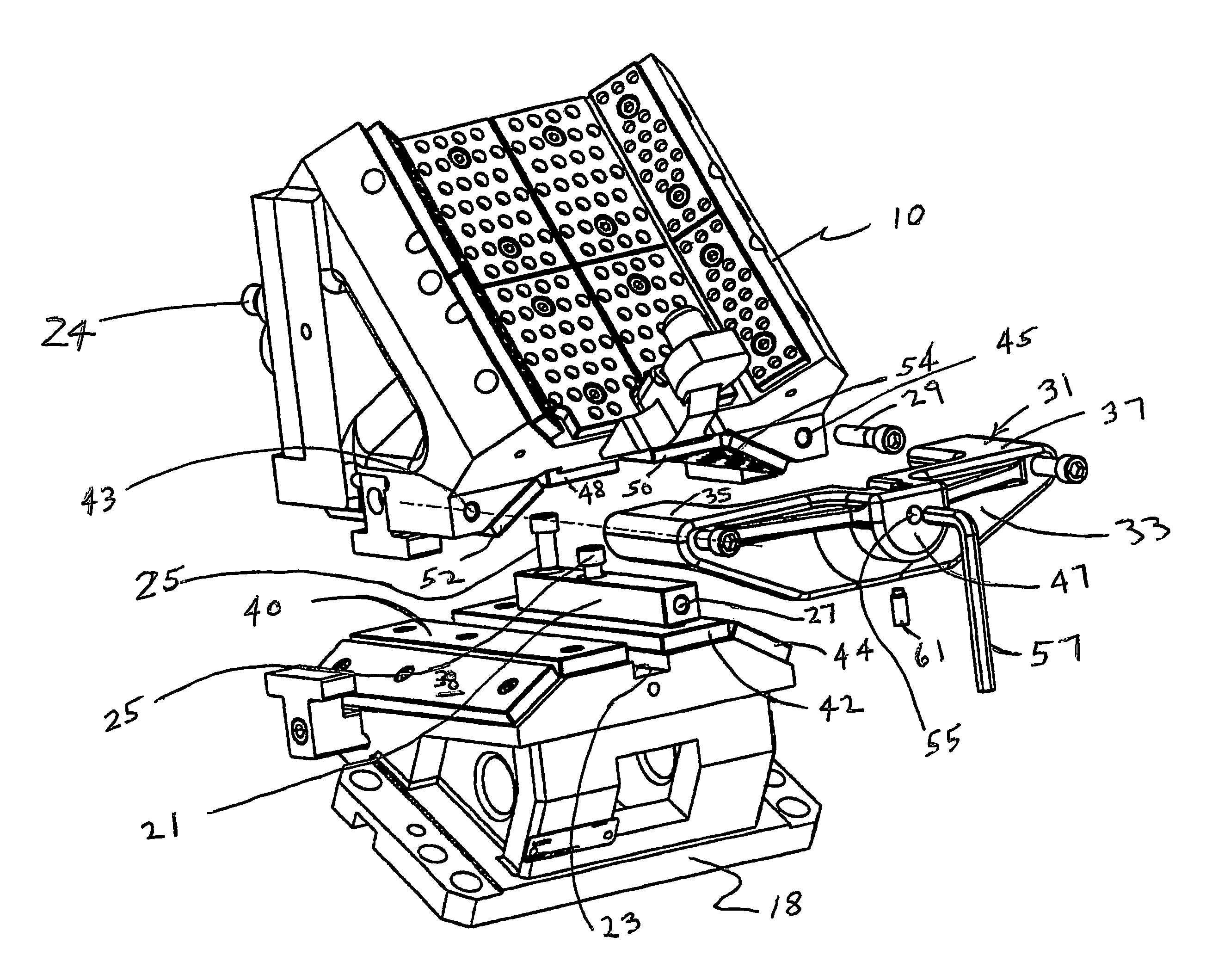
Figure 1 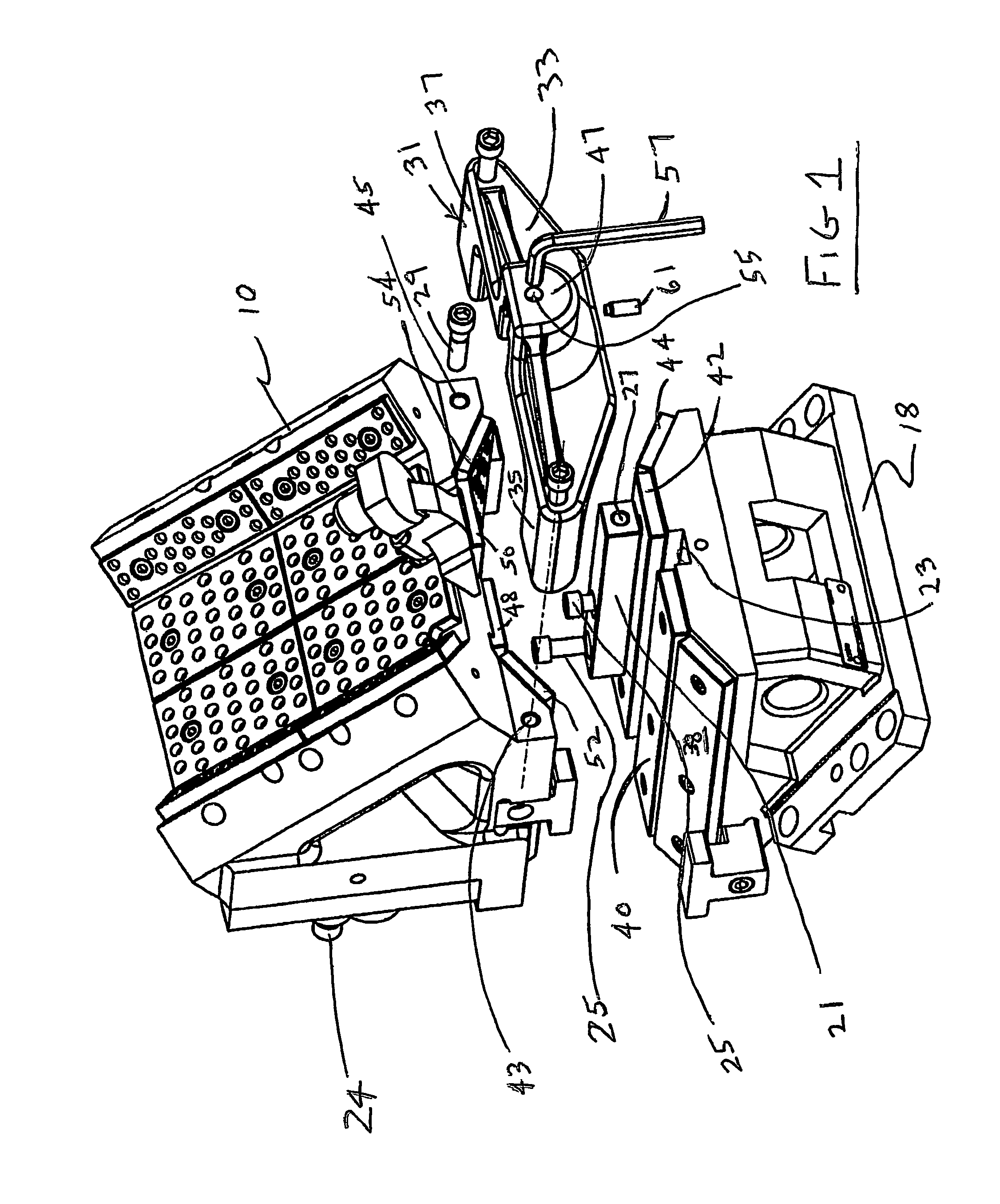
Figure 2 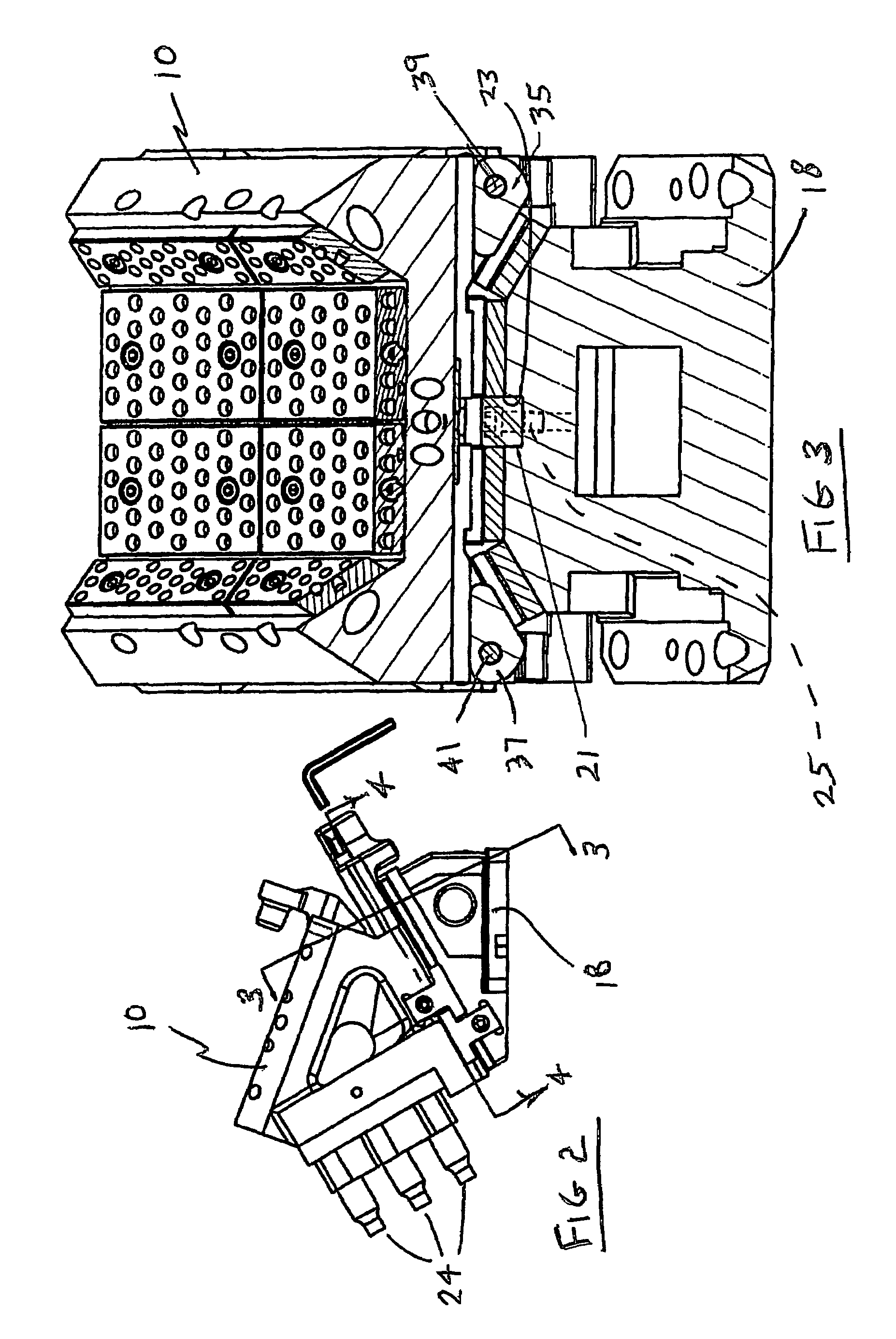
Figure 3
Abstract
Description
BACKGROUND OF THE INVENTION
[0001] 1. Field of the Invention
[0002] This invention relates to the set up of aerial cams in presses for forming sheet metal.
[0003] 2. Background Art
[0004] Aerial cams such as shown in U.S. Pat. Nos. 5,884,521; 5,487,296; 5,101,705 and 5,231,907 have been used for several years in sheet metal stamping operations to facilitate what might be termed secondary operations such as piercing holes, or the deformation of the metal panel (the workpiece) in a fashion that could not be performed by the action of the main dies in the press. The tools which perform such secondary operations are mounted on what is termed a slide, or tool holder, suspended from a cam adapter which is mounted on the upper shoe of the die set. As the upper shoe descends, the slide is carried downwardly and against a driver fastened to the lower die shoe of the press. The angles between the contacting faces of the slide, cam adapter and driver are such that the tool holder is shifted laterally ...
Examples
Embodiment Construction
)
[0016]In U.S. Pat. No. 5,884,521, incorporated herein by reference, and hereinafter the —521 patent, an aerial cam is shown in FIGS. 1 and 2 attached to and between the upper shoe or platen 14 of a sheet metal stamping press, and the lower shoe or platen 20. For clarity of illustration the main forming dies of the press are not shown. A portion of the workpiece, WP, is shown on a workpiece holder WPH, and a tool 24 in FIG. 3 of such patent moves against and retracts away from the workpiece upon, respectively, the descent and the rise of the upper shoe 14 of the press. A cam adapter 12 is fastened to the upper shoe to move therewith. Suspended from the cam adapter 12 is a tool holder 10 on which the tool or tools 24 are mounted which cooperate with the workpiece WP. When the press closes, the upper shoe descends and carries the tool holder 10 downwardly until the holder encounters the driver 18, whereupon the tool holder is shifted laterally (in relation to the path of movement of t...