
Reaming and stabilization tool and method for its use in a borehole
a stabilization tool and drilling tool technology, applied in the field of earth formation drilling, can solve the problems of reducing the life span and functionality of the underreamer, affecting the drilling fluid flow through the underreamer, and affecting the drilling effect, so as to achieve the effect of substantially reducing the disadvantages and eliminating the problems of the underreamer life span
Patent Information
- Authority / Receiving Office
- US · United States
- Patent Type
- Patents(United States)
- Current Assignee / Owner
- Publication Date
- 2008-07-22
Smart Images
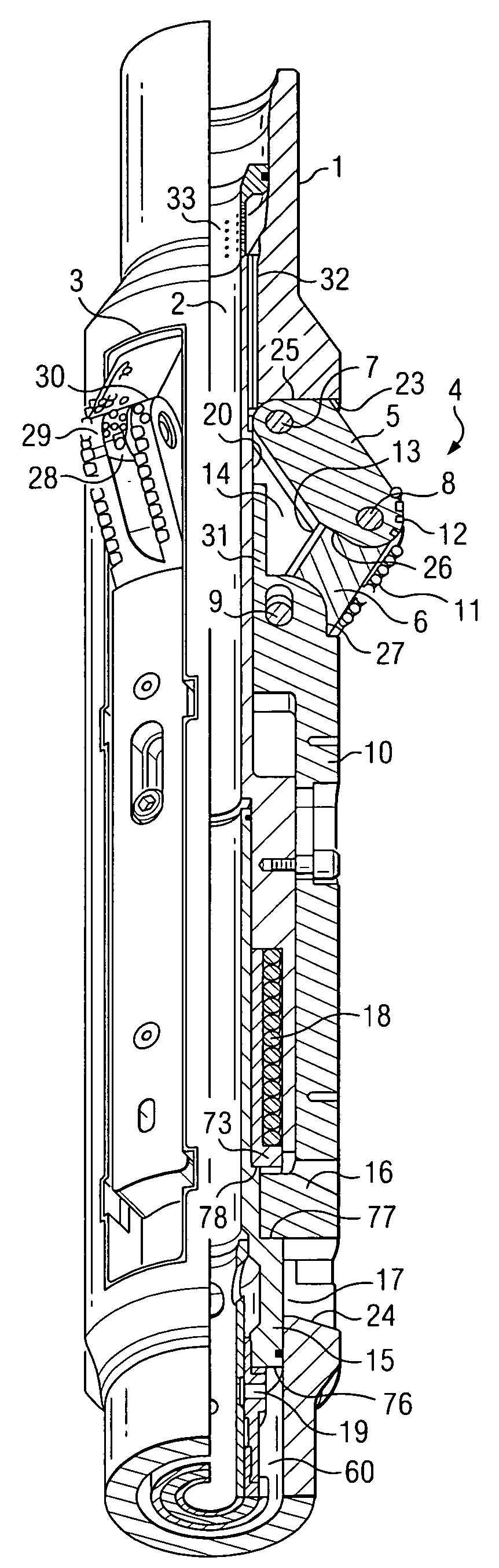
Figure 1 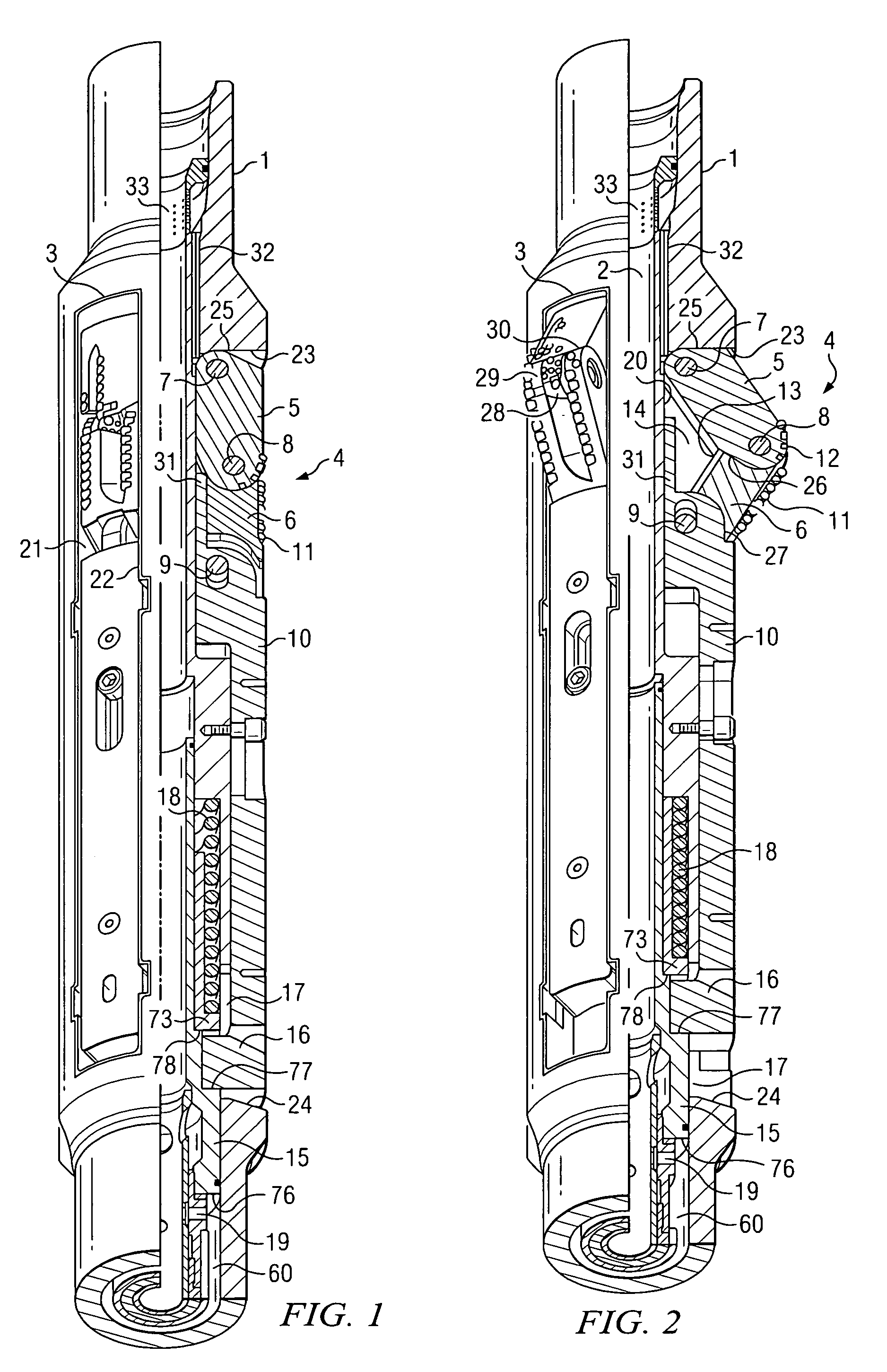
Figure 2 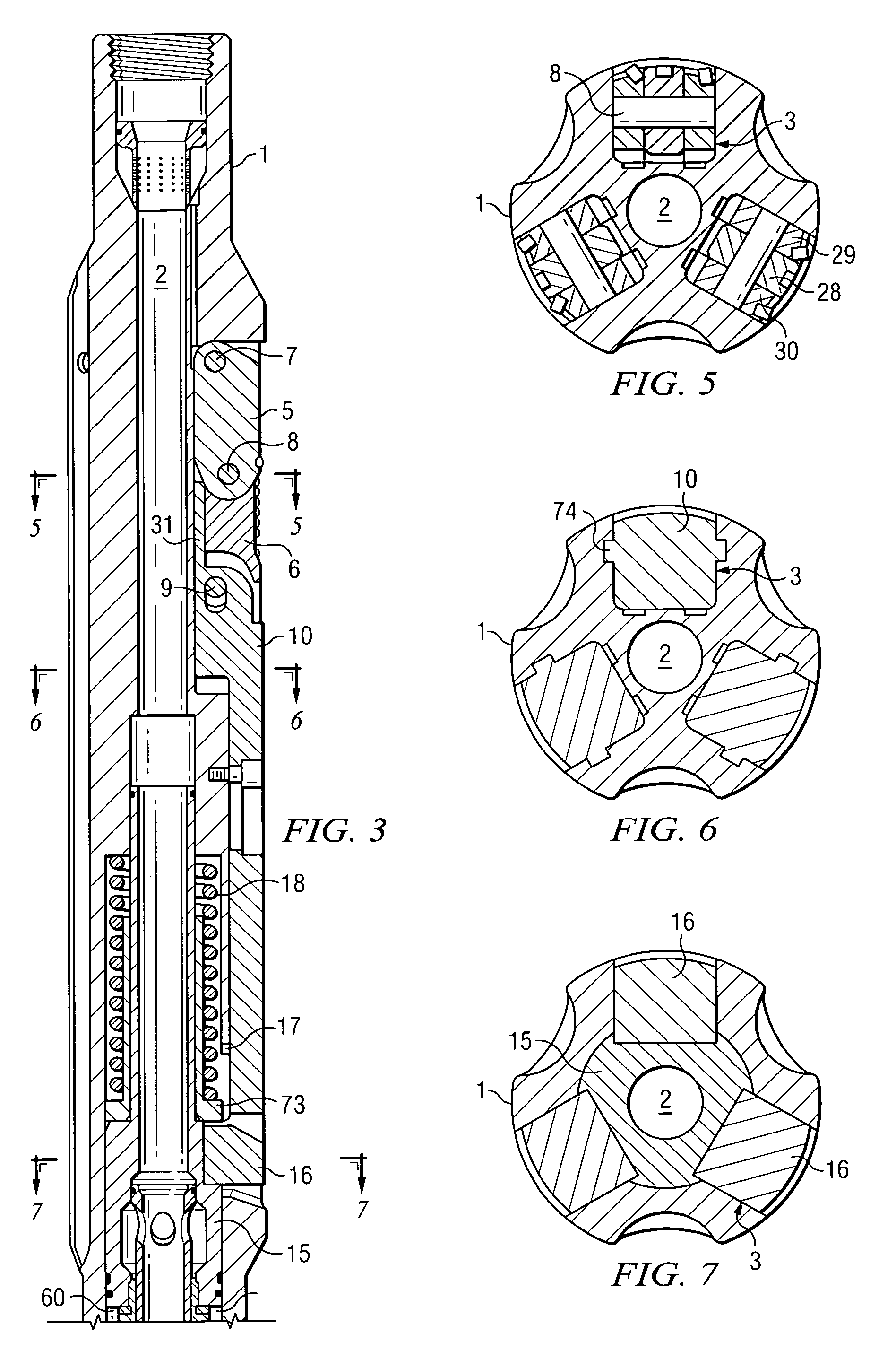
Figure 3
Abstract
Description
CROSS-REFERENCE TO RELATED APPLICATIONS
[0001] This application is a Continuation-in-Part of International Patent Application Serial No. PCT / BE2004 / 000083 entitled “Reaming and Stabilization Tool For Use in a Borehole” filed on Jun. 9, 2004.TECHNICAL FIELD OF THE INVENTION
[0002] This invention relates in general to earth formation drilling, and more particularly to a reaming and stabilization tool and method for its use in a borehole.BACKGROUND OF THE INVENTION
[0003] Earth formation drilling is often accomplished using a long string of drilling pipes and tools coupled together. The drilling string is rotated together in order to rotate a cutting bit at the end of the string. This cutting bit creates the hole which the rest of the drilling string moves through. For various reasons, it may be desirable to widen the walls of the hole after it has been created by the cutting bit. Bore-hole underreamers exist to accomplish the widening of the hole. An underreamer may be coupled to the drilli...
Examples
Embodiment Construction
[0026]The present invention relates to a reaming and stabilization tool to be used in a borehole. One embodiment of the present invention may include a tubular body to be mounted between a first section of a drill string and a second section of the drill string. The tubular body may have an axial cavity and, peripherally, housings provided with openings to the outside. A cutter element may be housed in each housing. The cutter element may include at least two cutting arms articulated on each other and on the tubular body. The cutting arms are able to be moved between a retracted position in which they are situated inside their housing and an extension position in which they are deployed outside.
[0027]The tool may also include a drive mechanism arranged inside the tubular body so as to be axially offset with respect to the cutter elements. The drive mechanism is capable of effecting a movement between two extreme positions. The tool may also include a transmission mechanism capable o...