
Quiet load for motor testing
Patent Information
- Authority / Receiving Office
- US · United States
- Current Assignee / Owner
- Publication Date
- 2009-09-22
- Estimated Expiration
- Not applicable · inactive patent
Smart Images
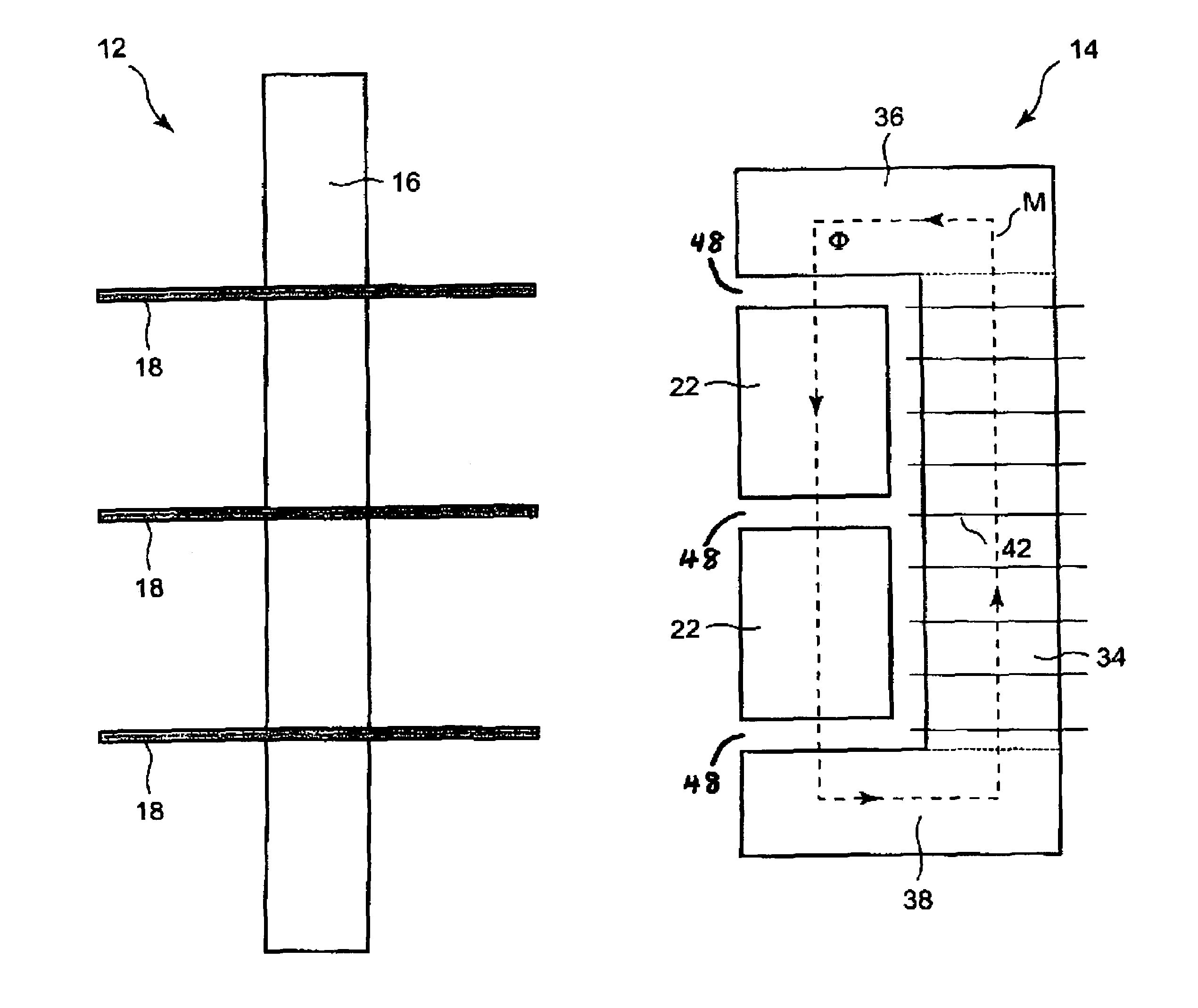
Figure 1 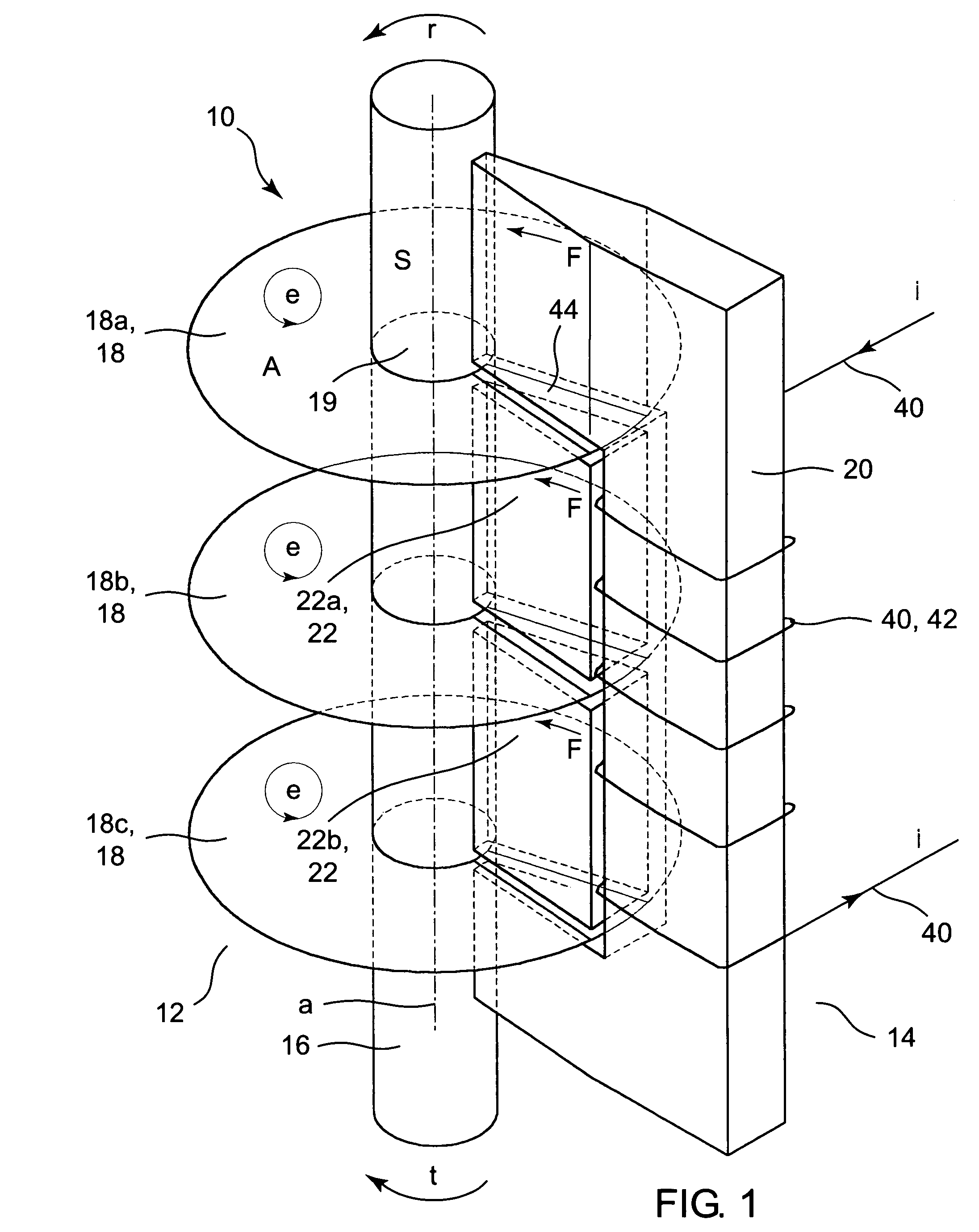
Figure 2 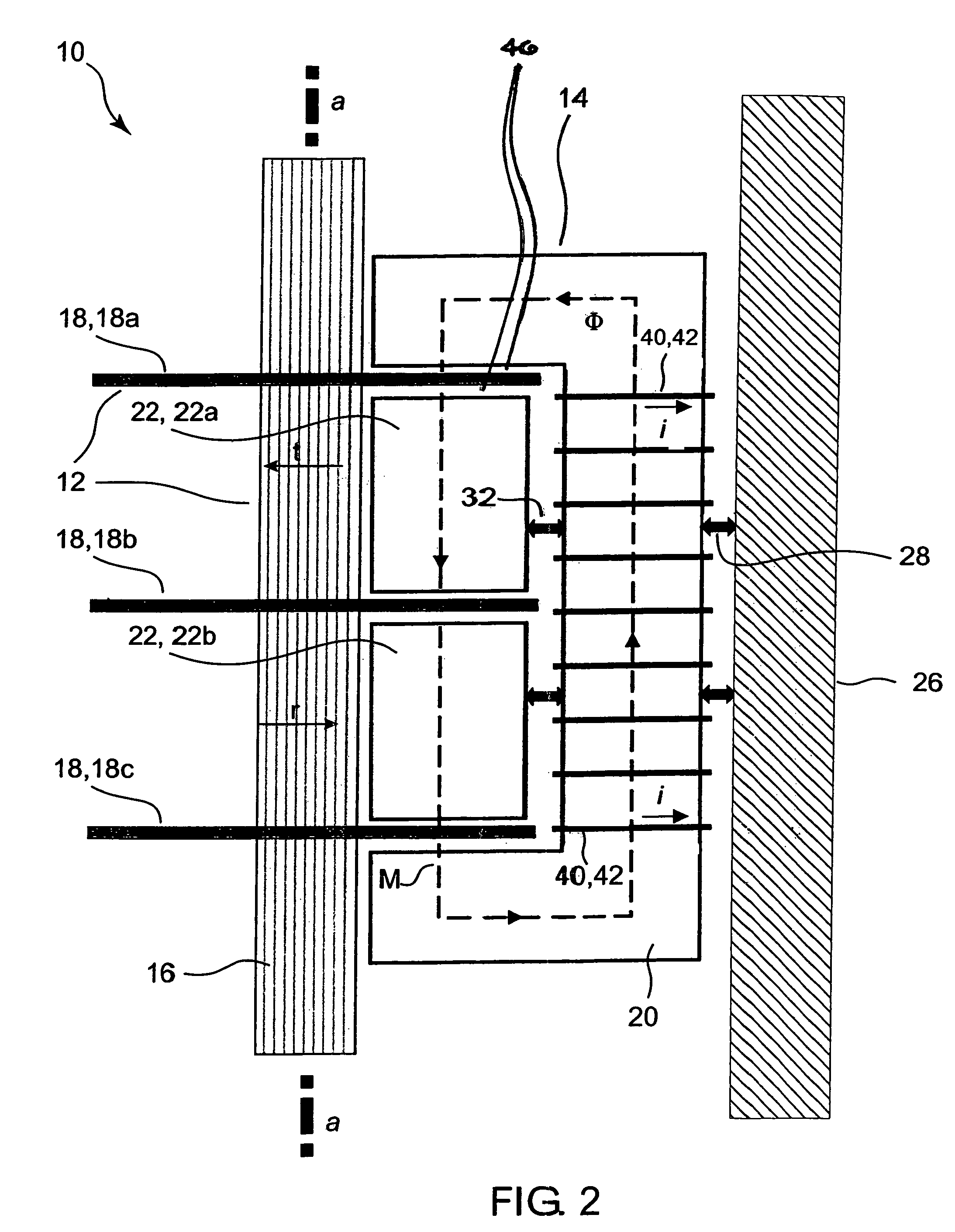
Figure 3
Abstract
Description
STATEMENT OF GOVERNMENT INTEREST
[0001] The invention described herein may be manufactured and used by or for the Government of the United States of America for governmental purposes without the payment of any royalties thereon or therefor.BACKGROUND OF THE INVENTION
[0002] The present invention relates to machines (e.g., motors) that include rotational members, more particularly to methods and apparatuses for imposing torque loading upon a rotational member for purposes of conducting testing (such as involving vibration, e.g., acoustic vibration) of a machine.
[0003] Vibration, such as sound vibration (e.g., that which produces noise), is an important consideration in the operation of various types of machinery. The current methodologies for providing a torque load for vibration testing of machines such as motors are deficient in terms of induced load smoothness, heat generation and vibration generation. The devices conventionally used for motor testing include Prony brakes, water brakes...
Examples
Embodiment Construction
[0023]Referring now to FIG. 1 through FIG. 7, inventive device 10 comprises a rotational unit 12 and at least one stationary unit 14. Rotational unit 12 and stationary unit 14 are separately shown in FIG. 5 and FIG. 6, respectively. Rotational unit 12 includes rotational shaft 16 and at least two electrically conductive disks 18. Each stationary unit 14 includes a bracket-shaped electromagnetic core 20 and at least one wedge-shaped guide block 22. For illustrative purposes, only one stationary unit 14 is shown in FIG. 1 and FIG. 2; however, according to more typical inventive practice, inventive device 10 includes plural (e.g., several or many) stationary units 14, circumferentially arranged such as exemplified in FIG. 3 and FIG. 4.
[0024]Stationary units 14 are shown in FIG. 3 and FIG. 4 to be arranged at approximately ninety degree angles and to be symmetrical with respect to geometric longitudinal rotational axis a of shaft 16. Inventive practice permits utilization of one or prac...