
AC-DC converter
a converter and ac-dc technology, applied in the direction of electric variable regulation, process and machine control, instruments, etc., can solve the problems of disadvantageous defects of ac-dc converters, disadvantageous output voltages of ac-dc converters, and low output voltages, so as to improve input power factor, reduce power consumption, and curb fluctuation of output voltage
Patent Information
- Authority / Receiving Office
- US · United States
- Patent Type
- Patents(United States)
- Current Assignee / Owner
- Publication Date
- 2013-10-22
Smart Images
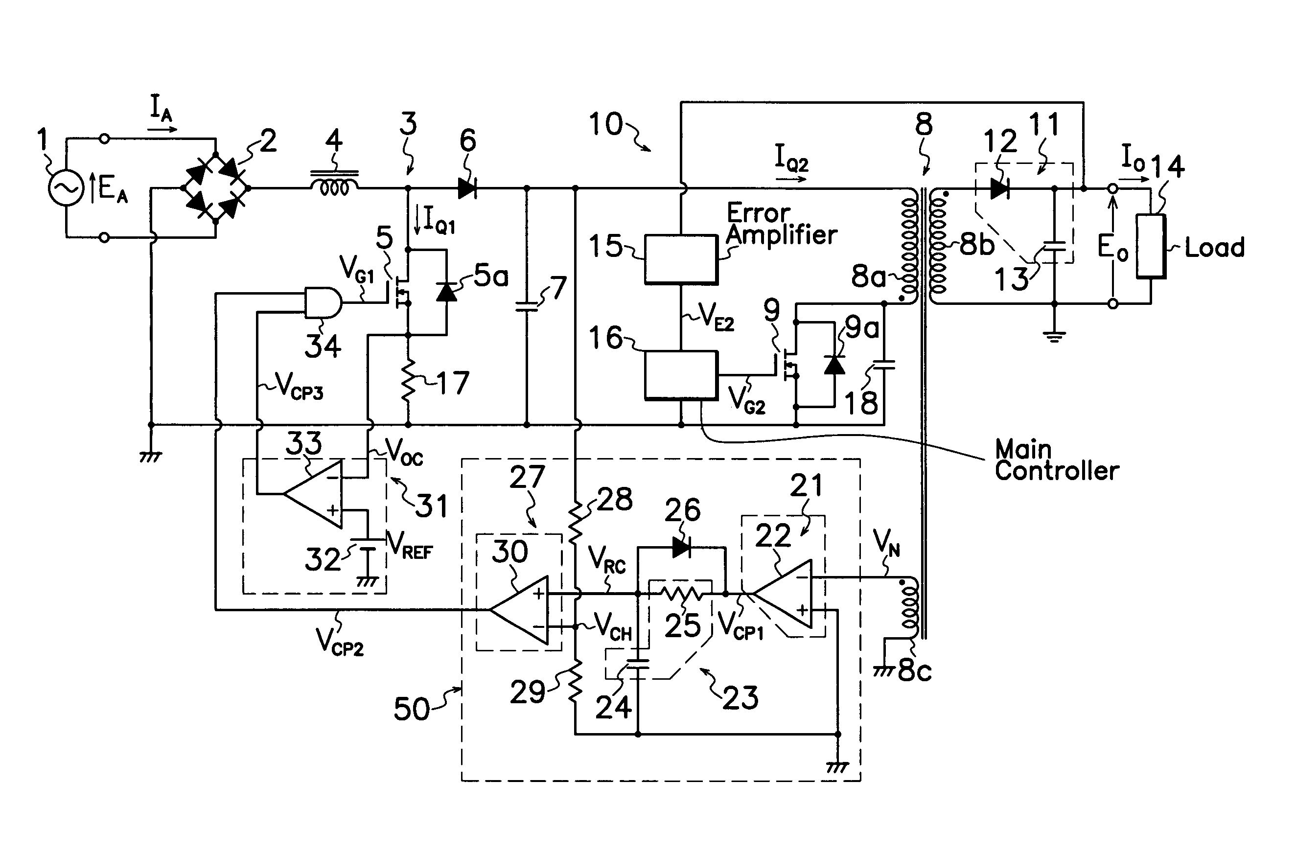
Figure 1 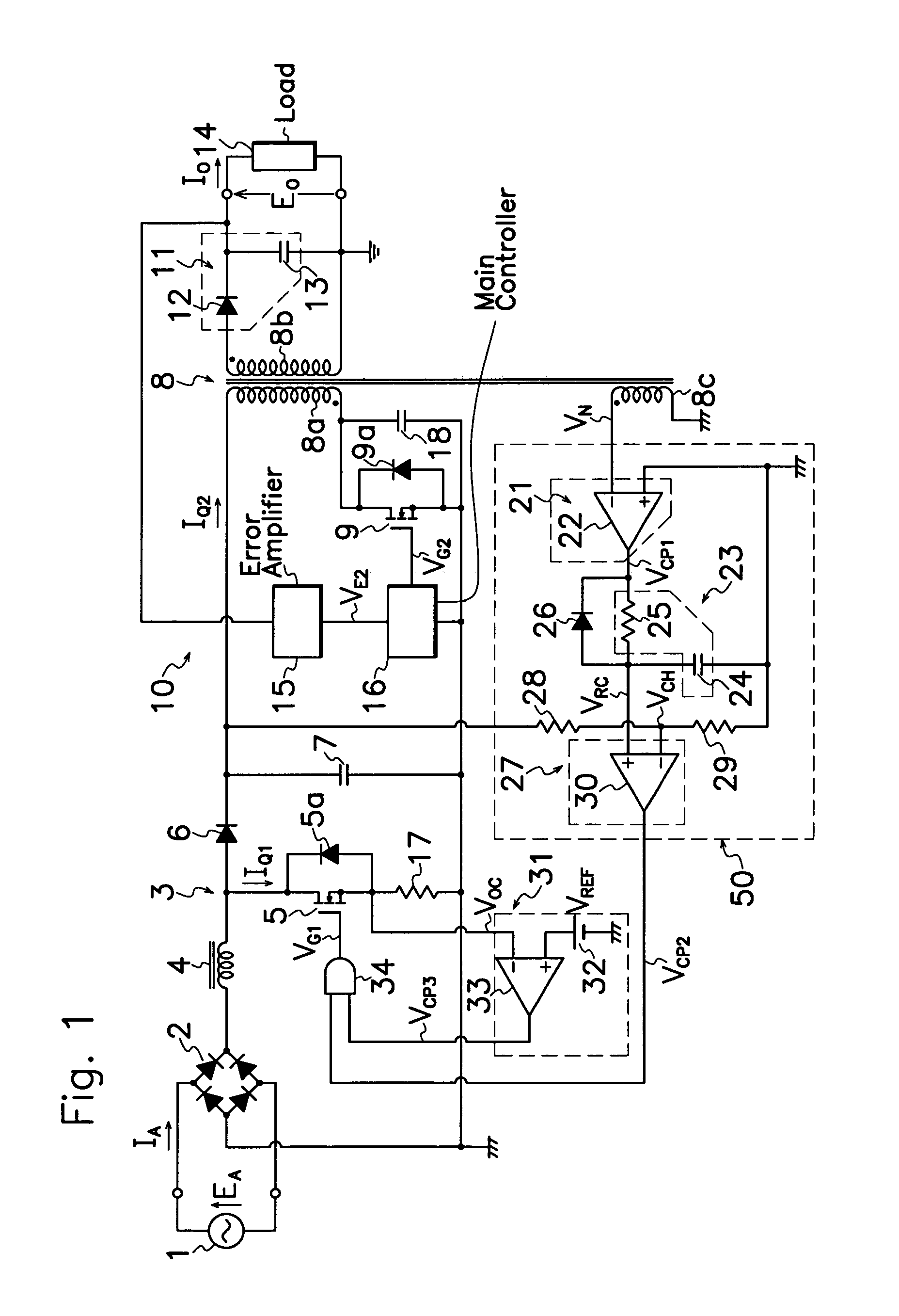
Figure 2 
Figure 3
Abstract
Description
TECHNICAL FIELD IN INDUSTRY
[0001] This application is a U.S. national phase submission of Patent Cooperation Treaty PCT / JP2008 / 054467 under 35 U.S.C. 371 based on Japanese Patent Application No. 2007-157936 filed 14 Jun. 2007. This invention relates to an AC-DC converter of the type capable of improving the input power factor relative to AC voltage and also reducing the consumption power during light load period while controlling fluctuation in output voltage from a boosting chopper circuit under variation in AC input voltage.PRIOR ART
[0002] AC-DC converters have been widely used in the past which comprises a rectification circuit for commutating AC voltage from an AC power source, a DC-DC converter for producing a DC voltage from an output voltage of the rectification circuit through a transformer and a rectification smoothing circuit by on-off operation of a switching element, and a boosting chopper circuit connected between the rectification circuit and DC-DC converter to improve i...
Examples
Embodiment Construction
[0023]An embodiment of the AC-DC converter according to the present invention is described hereinafter with reference to FIGS. 1 to 5 of the drawings. Same symbols are applied to substantially same parts in FIGS. 1 to 5 as those shown in FIGS. 6 and 7, and their explanation is omitted.
[0024]As shown in FIG. 1, the AC-DC converter according to the present embodiment comprises an auxiliary winding 8c in electro-magnetic coupling with primary winding 8a of transformer 8 shown in FIG. 6 in the adverse polarity, and a chopper control circuit (chopper controller) 50 connected to auxiliary winding 8c. Chopper controller 50 comprises a winding voltage detecting circuit (winding voltage detector) 21 for detecting voltage VN appearing on auxiliary winding 8c by on-off operation of main MOS-FET 9 in DC-DC converter 10 to produce an output signal VCP1 of high voltage level when auxiliary winding 8c produces one-sided or negative voltage VN, a waveform shaper 23 for generating a linearly rising ...