
DC regulated power supply comprising
a technology of dc regulated power supply and power supply circuit, which is applied in the direction of pulse technique, process and machine control, instruments, etc., can solve the problems of damage to load, input current also becomes dull, and the operation of the protection circuit influences other problems, so as to achieve the effect of suppressing the fluctuation of output voltag
Patent Information
- Authority / Receiving Office
- US · United States
- Patent Type
- Applications(United States)
- Current Assignee / Owner
- Publication Date
- 2005-09-29
- Estimated Expiration
- Not applicable · inactive patent
Smart Images
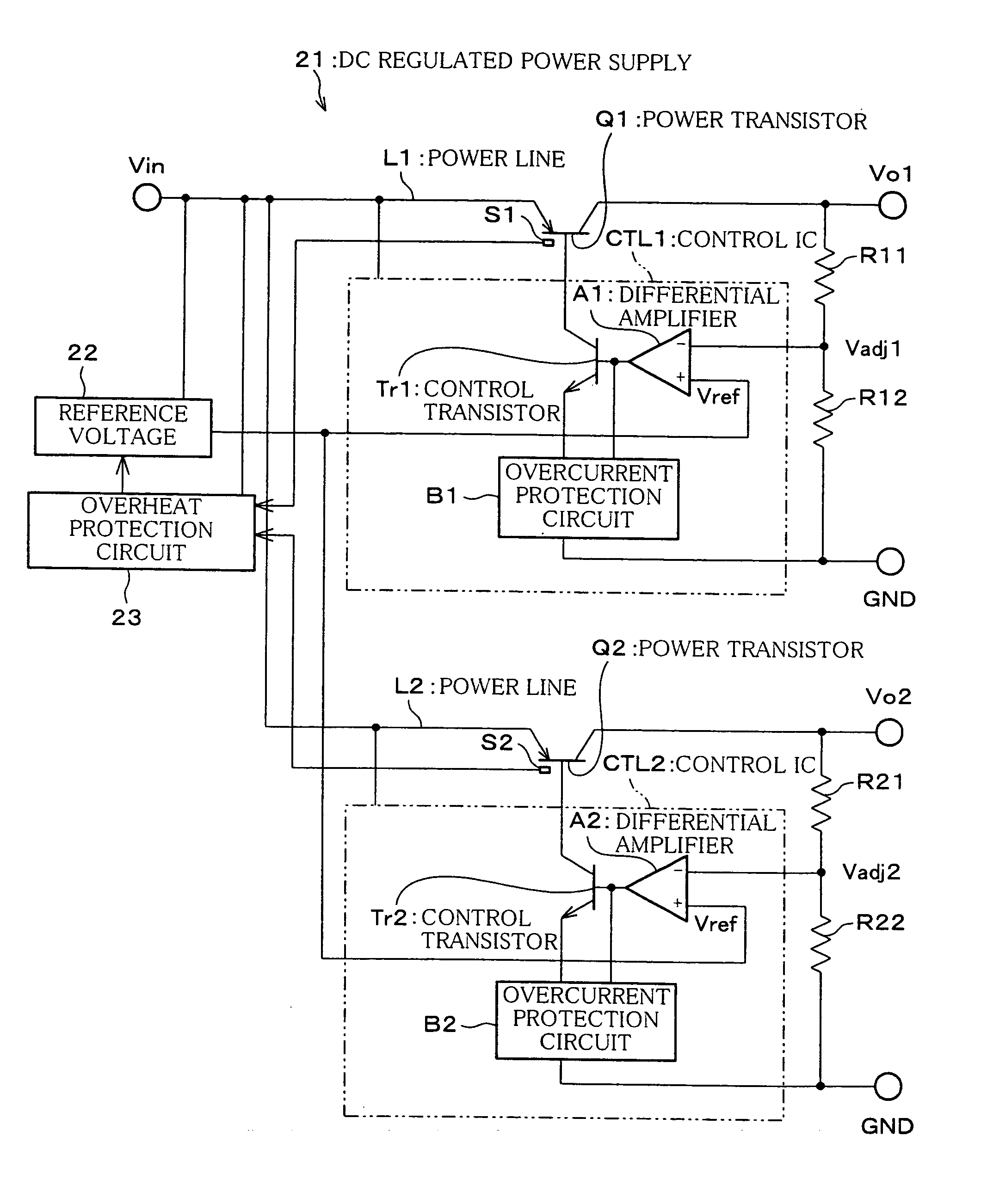
Figure 1 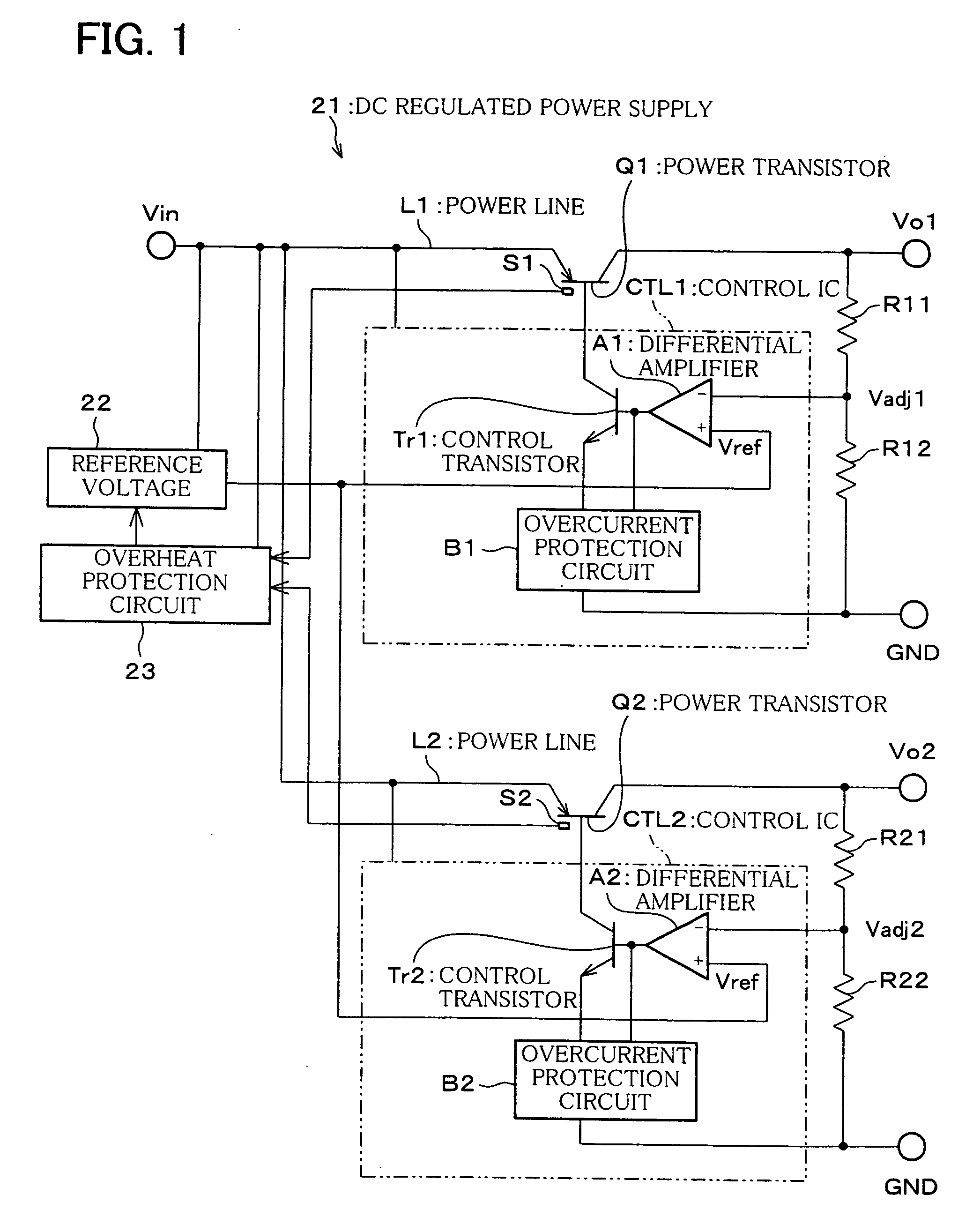
Figure 2 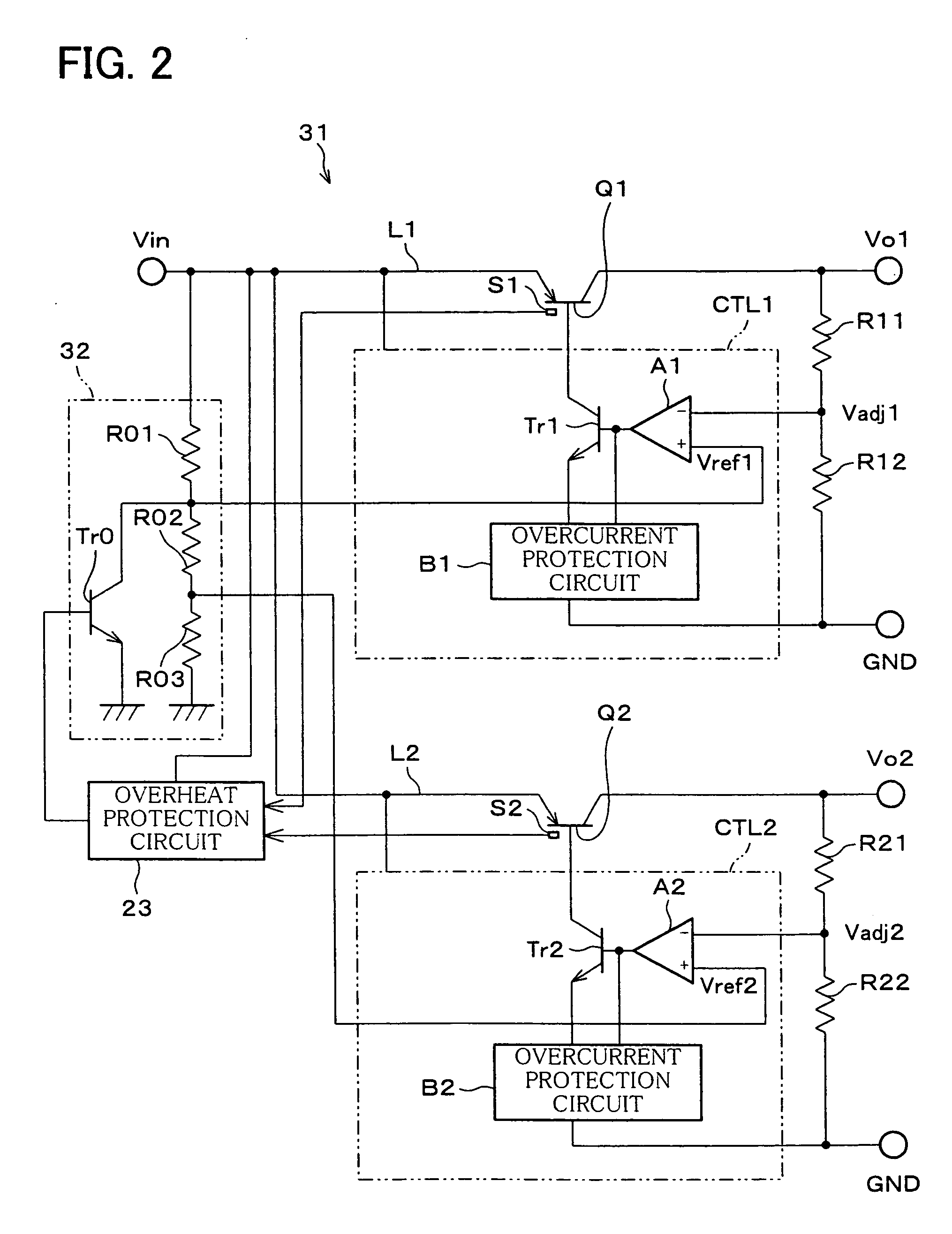
Figure 3
Abstract
Description
CROSS-REFERENCE TO RELATED APPLICATION
[0001] This application is a Divisional of co-pending application Ser. No. 10 / 608,565, filed on Jun. 30, 2003, the entire contents of which are hereby incorporated by reference and for which priority is claimed under 35 U.S.C. § 120.FIELD OF THE INVENTION
[0002] The present invention relates to a DC regulated power supply of a dropper-type, known as a series regulator, and particularly to a structure for the protection against overheating in such a DC regulated power supply with outputs of plural systems. BACKGROUND OF THE INVENTION
[0003] FIG. 6 is a block diagram illustrating a basic electrical structure of a dropper-type DC regulated power supply 1. The DC regulated power supply 1 is a three-terminal regulator with a single output, in which a power transistor q is interposed in series on a power line 1 that connects a power supply with a load (neither is shown). The base current of the power transistor q is controlled by a control IC ctl. In ...
Examples
first embodiment
[0035] Referring to FIG. 1, the following describes one embodiment of the present invention.
[0036]FIG. 1 is a block diagram illustrating an electrical structure of a DC regulated power supply 21 of the First Embodiment of the present invention. The DC regulated power supply 21 is a regulated power supply of a dropper type, in which output voltages Vo1, Vo2 of two systems are produced from a common input voltage Vin.
[0037] The output voltages Vo1, Vo2 of two systems may have the same level or different levels. Likewise, the current capacitance may be the same or different. Further, the number of systems is not just limited to two, and outputs of three or more systems may be used.
[0038] Power transistors Q1, Q2 are serially and respectively connected to power lines L1, L2 that connect a common power supply (not shown) to their respective loads. Control ICs CTL1, CTL2 are provided to control the base currents of the power transistors Q1, Q2, respectively. By controlling the base cur...
second embodiment
[0046] The following describes another embodiment of the present invention.
[0047]FIG. 2 is a block diagram illustrating an electrical structure of a DC regulated power supply 31 of the Second Embodiment of the present invention. The DC regulated power supply 31 is similar to the DC regulated power supply 21, and accordingly corresponding elements are given the same reference numerals and explanations thereof are omitted here.
[0048] What should be noted about the DC regulated power supply 31 is that a reference voltage source 32 generates two reference voltages Vref1, Vref2, and supplies these voltages respectively to differential amplifiers A1, A2. In the example of FIG. 2, the voltages produced by dividing the input voltage Vin through resistors R01, R02, and R03 are Vref1 and Vref2, which are related to each other by Vref1>Vref2.
[0049] Further, in the reference voltage source 32, a control transistor Tr0 is provided parallel to the resistors R02, R03. The control transistor Tr0...
third embodiment
[0053] The following describes an electrical structure of a DC regulated power supply 41 of the Third Embodiment of the present invention. The DC regulated power supply 41 is similar to the foregoing DC regulated power supply 21, and accordingly corresponding elements are given the same reference numerals and explanations thereof are omitted here.
[0054] What should be noted about the DC regulated power supply 41 is that switches SW1, SW2 are respectively provided for the lines of reference voltage Vref supplied to the differential amplifiers A1, A2 from the reference voltage source 22, and that the switches SW1, SW2 are controlled by the overheat protection circuit 43. Further, in addition to controlling the switches SW1, SW2, the overheat protection circuit 43 in the DC regulated power supply 43 is provided with a delay circuit, so as to vary ON timings of the switches SW1, SW2 when reverting to a normal state from an overheated state.
[0055] Thus, detecting an overheated state, t...