
DC/DC converter
a converter and converter technology, applied in the direction of dc-dc conversion, power conversion systems, instruments, etc., can solve the problems of high duty ratio of each channel, poor stability of output voltage, and large amount of current, so as to suppress the fluctuation of output voltag
Patent Information
- Authority / Receiving Office
- US · United States
- Patent Type
- Patents(United States)
- Current Assignee / Owner
- Publication Date
- 2018-02-13
Smart Images
Figure 1 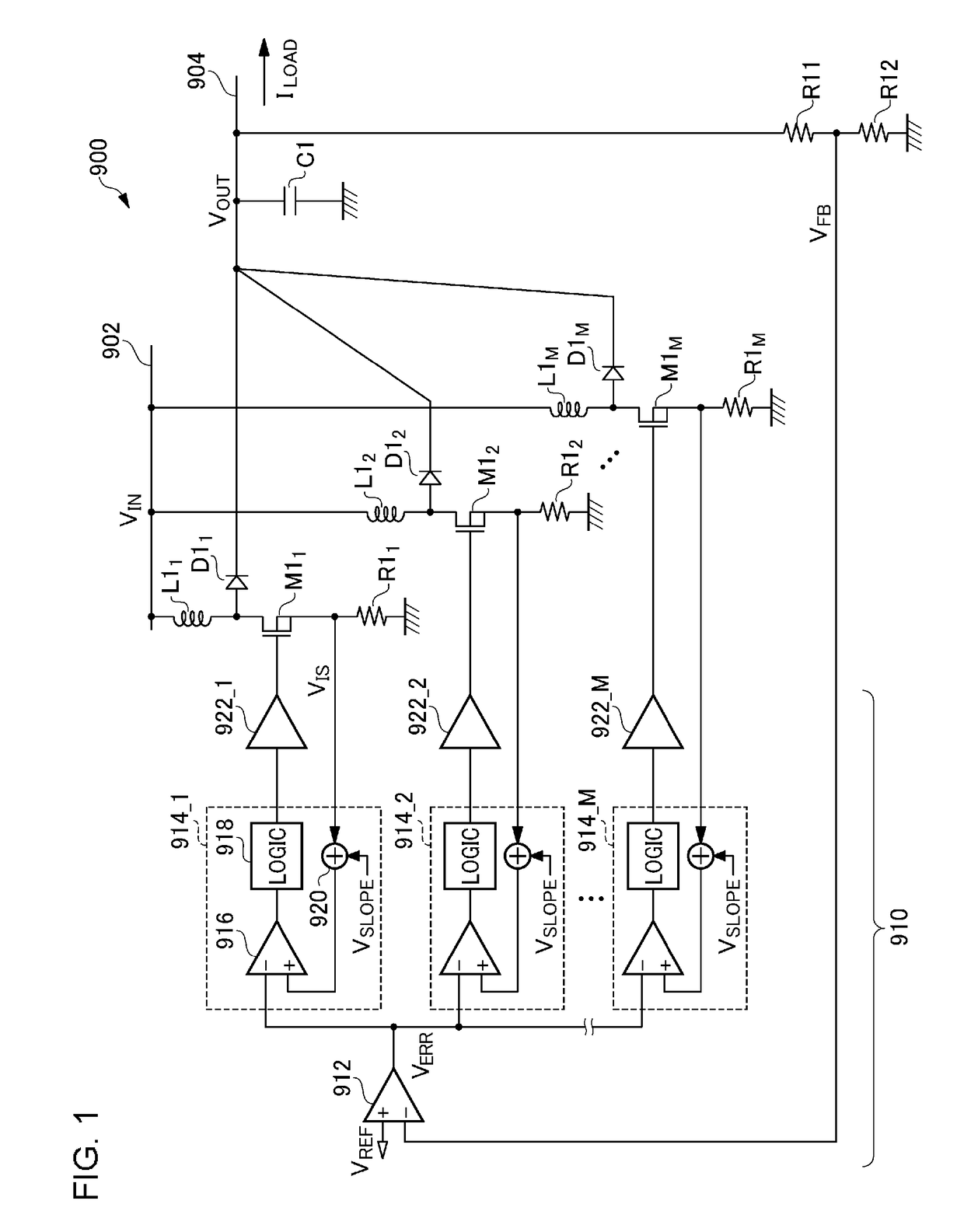
Figure 2 
Figure 3
Abstract
Description
CROSS REFERENCE TO RELATED APPLICATIONS
[0001] The present invention claims priority under 35 U.S.C. § 119 to Japanese Application No. 2016-012711, filed Jan. 26, 2016, the entire content of which is incorporated herein by reference.BACKGROUND OF THE INVENTION
[0002] 1. Field of the Invention
[0003] The present invention relates to a DC / DC converter.
[0004] 2. Description of the Related Art
[0005] Various kinds of electronic devices employ a DC / DC converter that converts a DC voltage having a given voltage value into a DC voltage having a different voltage value. In order to suppress ripple in the input current of the DC / DC converter, a multi-phase DC / DC converter is employed. FIG. 1 is a circuit diagram showing a multi-phase step-up (boost) DC / DC converter (which will simply be referred to as the “DC / DC converter”) 900. The DC / DC converter 900 receives a DC input voltage VIN via an input line 902, and generates a stepped-up voltage VOUT at an output line 904. The DC / DC converter 900 is confi...
Examples
first modification
[First Modification]
[0122]The current balance circuit 220a shown in FIG. 10 may include an averaging circuit that generates an average value of the current detection signals VIS instead of the sample-and-hold circuits 222. Such an averaging circuit may be configured as a low-pass filter.
second modification
[Second Modification]
[0123]Description has been made in the embodiment regarding a diode rectification DC / DC converter. Also, the present invention is applicable to a synchronous rectification DC / DC converter. Also, the present invention is applicable to a step-down DC / DC converter and a step-up / step-down DC / DC converter. In this case, the topology of the output circuit 110 shown in FIG. 3 may preferably be modified.
third modification
[Third Modification]
[0124]In FIG. 3, the detection method for detecting the coil current IL is not restricted in particular. For example, the on resistance of the switching transistor M1 may be used instead of the current sensing resistor R1. Also, an additional transistor may be provided as a replica of the switching transistor M1 such that a current flows through the replica transistor in proportion to the current that flows through the switching transistor M1. With such an arrangement, the current that flows through the replica transistor may be detected.