
Turbine shroud
a technology for turbines and shrouds, applied in the direction of machines/engines, liquid fuel engines, lighting and heating apparatus, etc., can solve the problems of affecting the performance of gas turbine engines, serious fuel economy problems, engine performance drop, etc., and achieve the effect of reducing the thermal stress of each shroud segmen
Patent Information
- Authority / Receiving Office
- US · United States
- Patent Type
- Patents(United States)
- Current Assignee / Owner
- Publication Date
- 2014-02-04
Smart Images
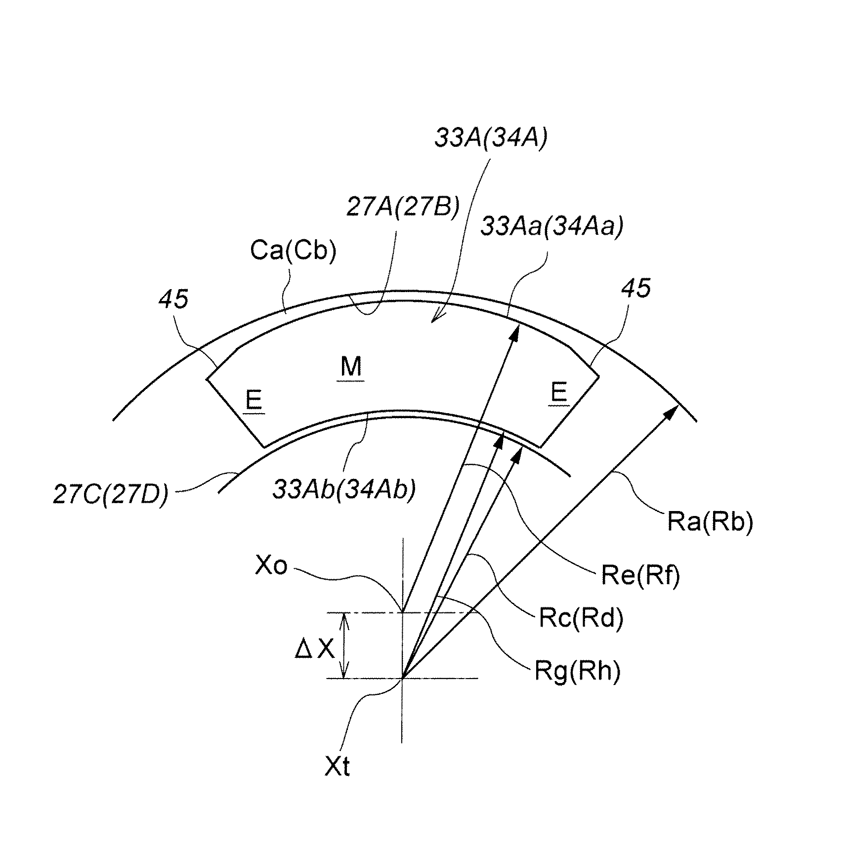
Figure 1 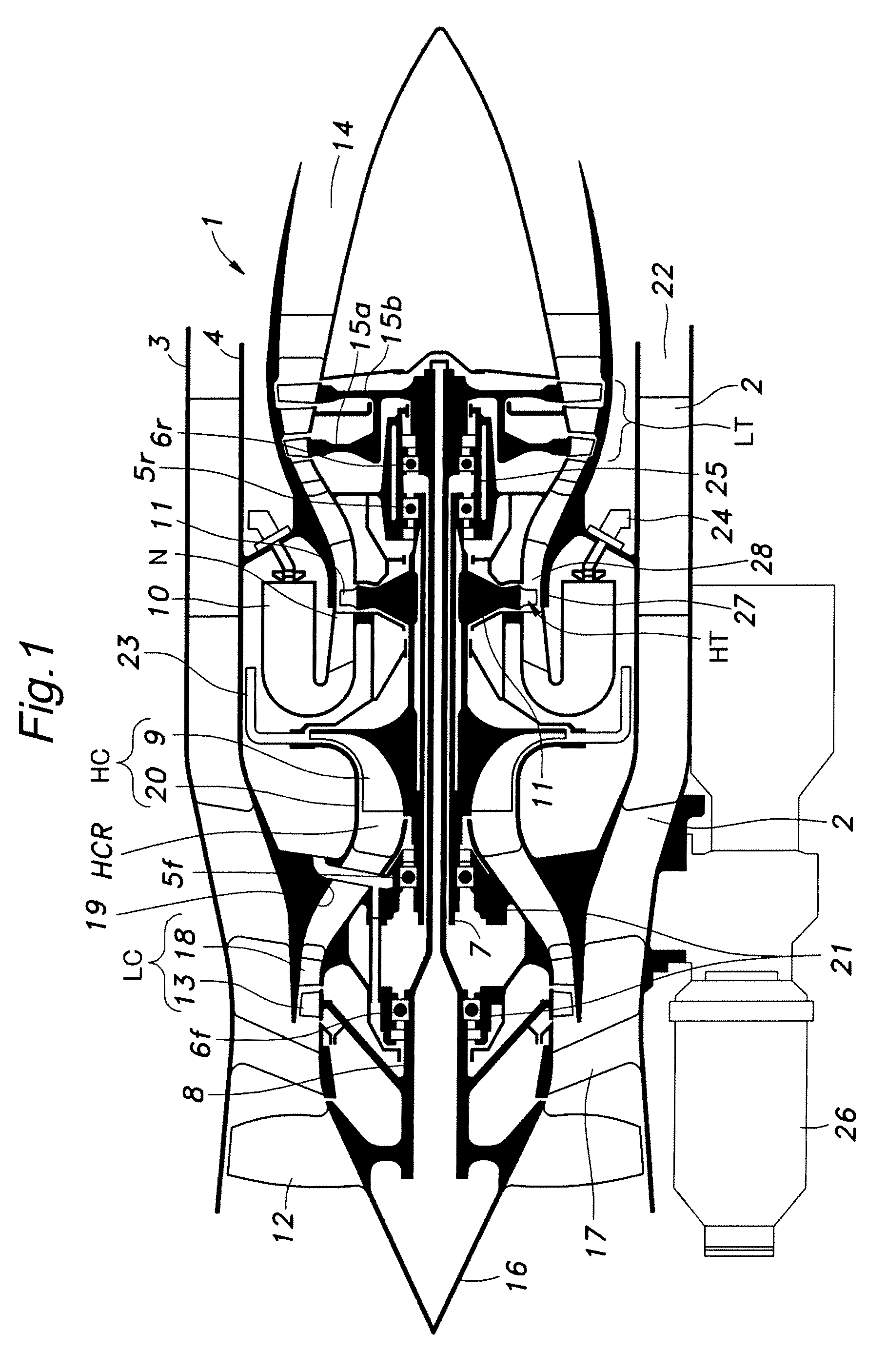
Figure 2 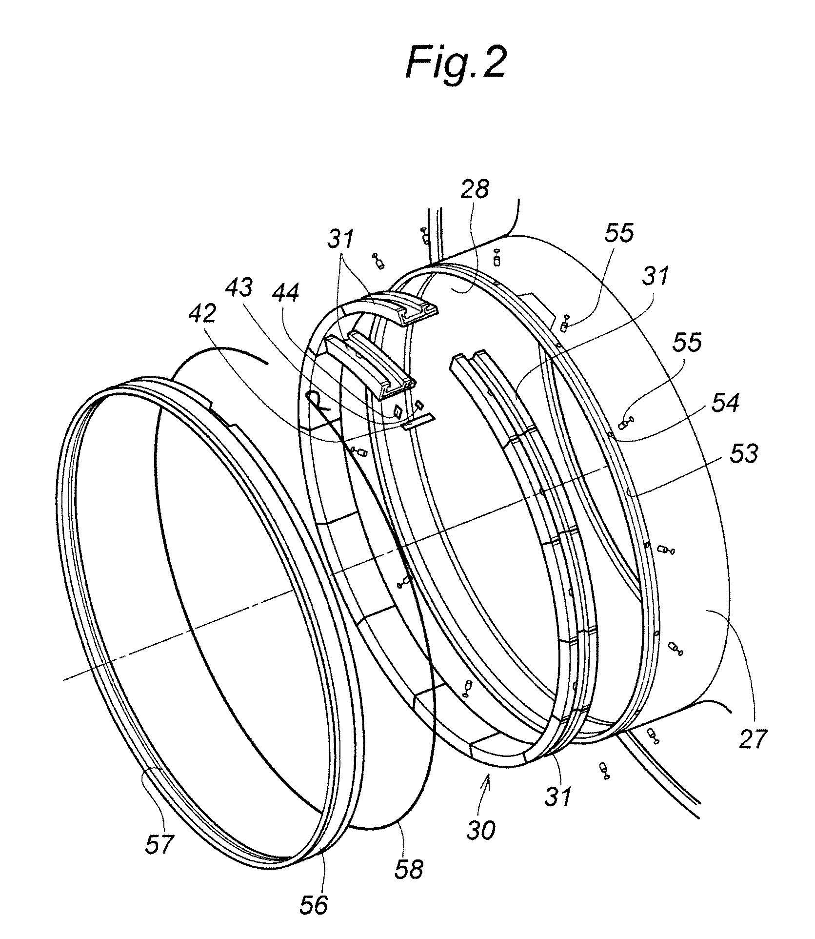
Figure 3
Abstract
Description
TECHNICAL FIELD
[0001] The present invention relates to a turbine shroud, and in particular to a turbine shroud that surrounds turbine rotor blades of a gas turbine engine and defines an annular cooling fluid chamber.BACKGROUND OF THE INVENTION
[0002] A high pressure turbine of a gas turbine engine is surrounded by an annular turbine shroud, and a small annular gap is defined between the outer tips of the turbine rotor blades and the opposing inner circumferential surface of the turbine shroud. Typically, a turbine shroud is formed by a plurality of arcuate shroud segments combined into an annular assembly, and attached to an inner peripheral wall of a turbine casing. See Japanese patent laid open publication No. 4-330302 and Japanese patent laid open publication No. 2000-54804, for instance.
[0003] A turbine shroud is exposed to combustion gas of a high temperature, and this causes a temperature gradient in a radial direction. The temperature gradient in turn causes an uneven thermal exp...
Examples
second embodiment
[0063]FIG. 9 shows the present invention. In this embodiment, the inner circumferential surfaces 27A and 27B of the annular axial slots 51 and 52 of the turbine casing 27 opposing the outer circumferential surfaces 33Aa and 34Aa of the front and rear axial walls 33A and 34A, respectively, are defined by cylindrical surfaces centered around the rotational center Xt of the turbine and having radii of Ra and Rb, respectively, and the outer circumferential surfaces 33Aa and 34Aa of the axial walls 33A and 34A are defined by non-cylindrical surfaces such as elliptic and parabolic surfaces that define a greater clearance in each circumferential end than in the circumferential middle part. The outer circumferential surfaces of the axial walls are each additionally formed with a planar sloping surface 45 at each circumferential end thereof.
[0064]In this case also, when the surrounding temperature is low, the clearance is greater in each circumferentially terminal end than in the circumferen...
third embodiment
[0066]FIGS. 10A and 10B show the present invention. In particular, FIG. 10A shows the state of a shroud segment 31 when the engine is cold, and FIG. 10B shows the state of the shroud segment 31 when the engine is warmed up. The shroud segment 31 is configured such that, when the engine is cold, the clearance Cc, Cd between the inner circumferential surface 33Ab, 34Ab of each axial wall 33A, 34A and opposing outer circumferential surface 27C, 27D of the annular axial slot 51, 52 is greater in a circumferential middle part M thereof than each circumferential end part thereof E.
[0067]In this case, whereas the outer circumferential surface 33Aa, 34Aa of each axial wall 33A, 34A consists of a cylindrical surface centered around the rotation center Xt of the turbines, the inner circumferential surface 33Ab, 34Ab of the axial wall 33A, 34A is centered around an axial center offset from the rotation center Xt of the turbines, and is given with a smaller curvature radius. The outer circumfer...
fourth embodiment
[0070]FIGS. 11A and 11B show the present invention. In particular, FIG. 11A shows the state of a shroud segment 31 when the engine is cold, and FIG. 11B shows the state of the shroud segment 31 when the engine is warmed up. The shroud segment 31 is configured such that, when the engine is cold, the clearance Cc, Cd between the inner circumferential surface 33Ab, 34Ab of each axial wall 33A, 34A and opposing outer circumferential surface 27C, 27D of the annular axial slot 51, 52 is greater in a circumferential middle part M thereof than in each circumferential end part thereof E, and, additionally, the clearance Ca, Cb between the outer circumferential surface 33Aa, 34Aa of each axial wall 33A, 34A and opposing inner circumferential surface 27A, 27B of the annular axial slot 51, 52 is greater in each circumferential end part thereof E than in a circumferential middle part M thereof.
[0071]In this case also, when the engine is warmed up, the thermal deformation of the shroud segment 31...