
Hot dry rock generation system
a technology of hot dry rock and generation system, which is applied in the direction of mechanical power devices, mechanical equipment, mechanical devices, etc., can solve the problems of large white smoke generation, crack formation in hot dry rock, and operators who work in the neighborhood of the collecting tank b>4/b> being exposed to danger, so as to save energy
Patent Information
- Authority / Receiving Office
- US · United States
- Patent Type
- Patents(United States)
- Current Assignee / Owner
- Publication Date
- 2014-03-04
- Estimated Expiration
- Not applicable · inactive patent
Smart Images
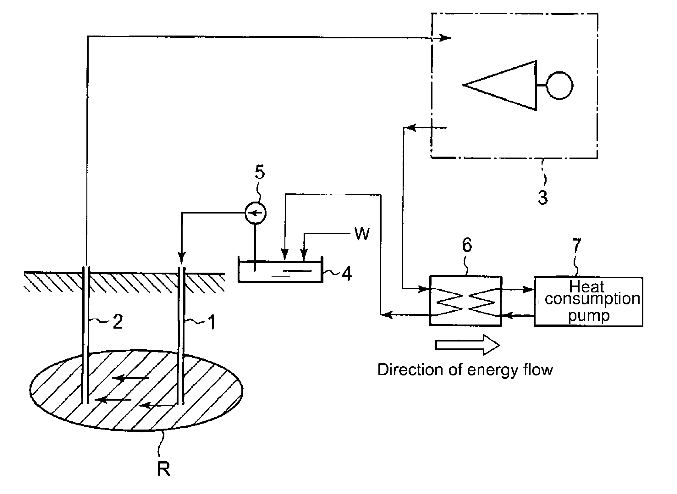
Figure 1 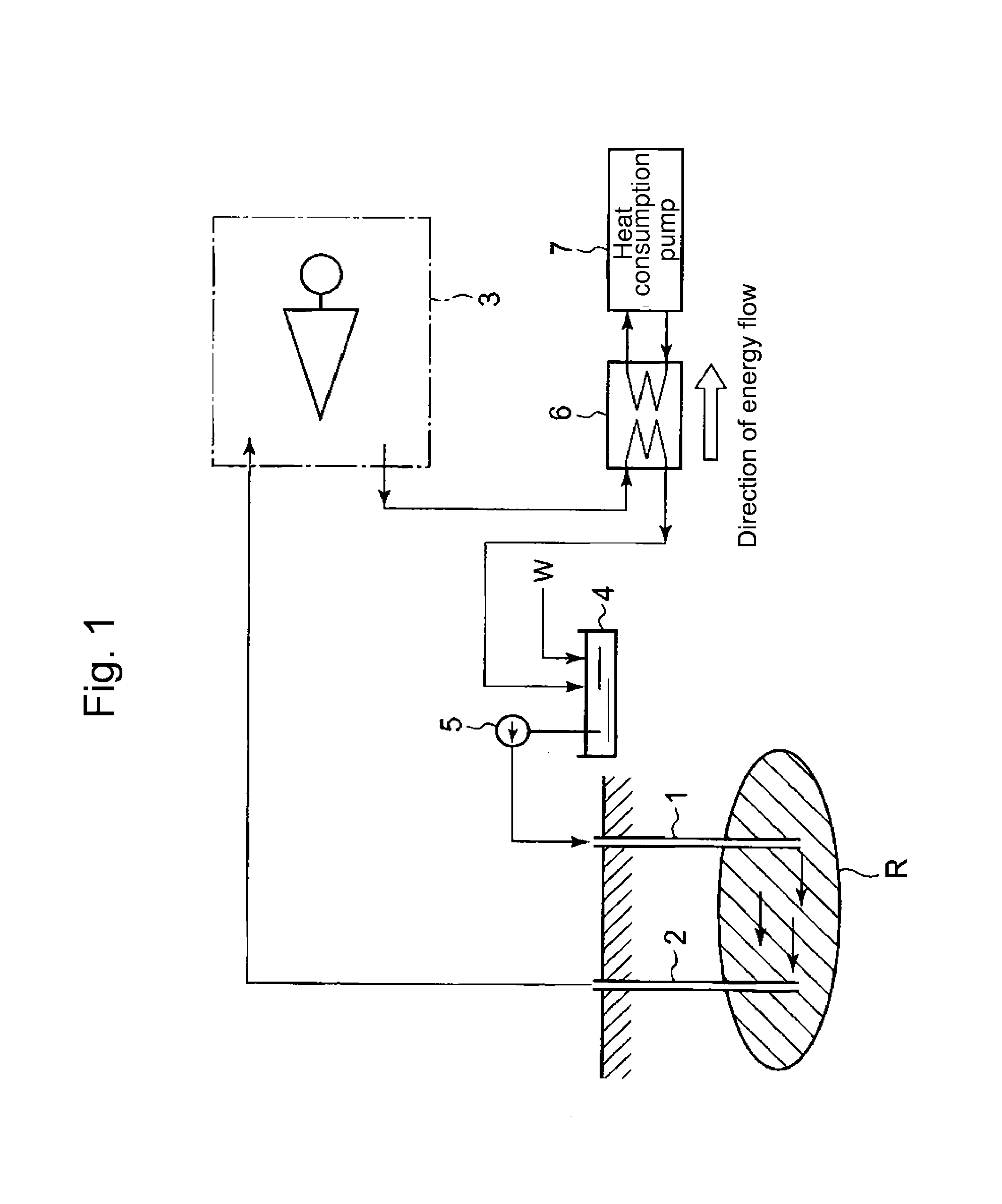
Figure 2 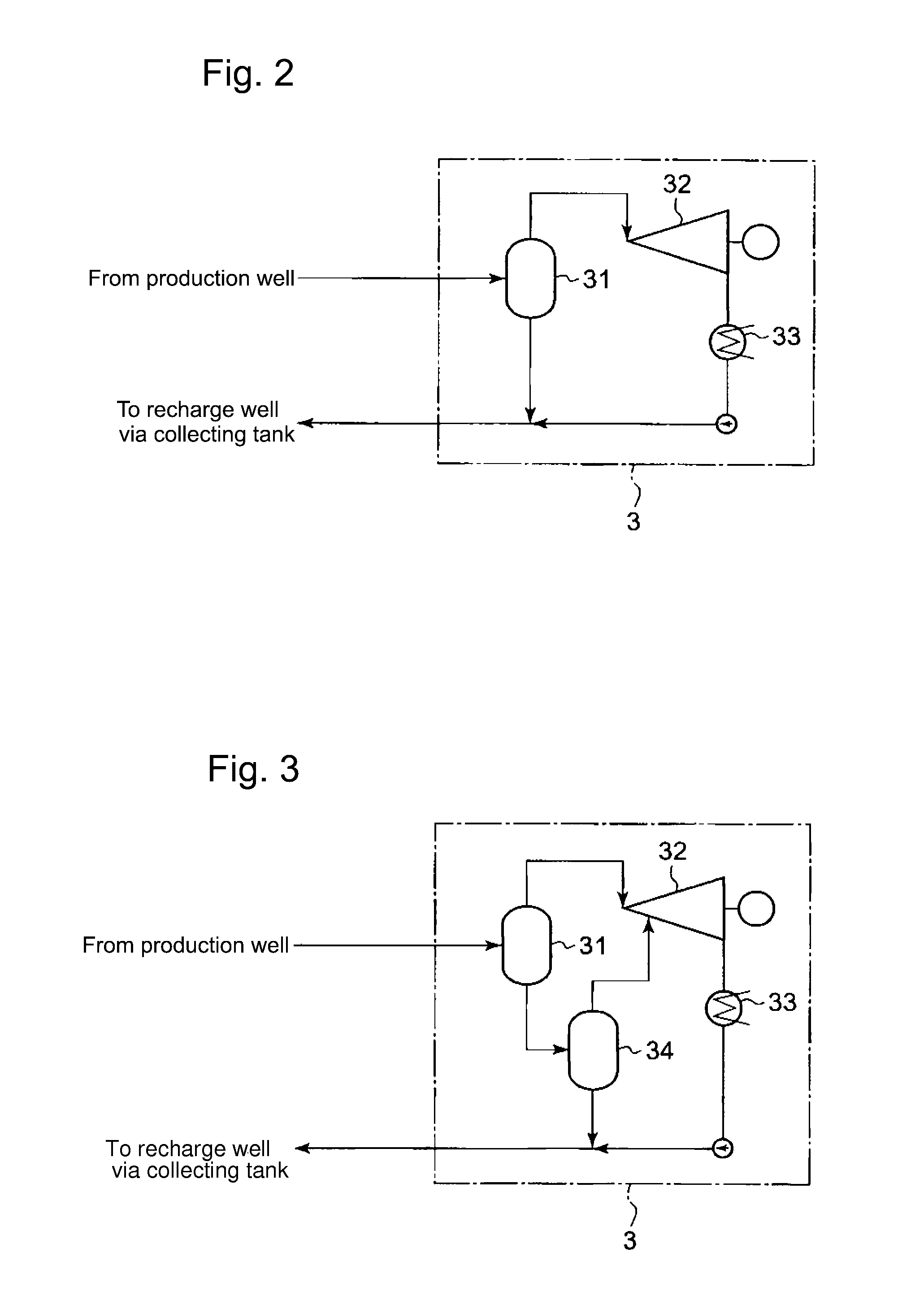
Figure 3
Abstract
Description
BACKGROUND OF THE INVENTION
[0001] 1. Field of the Invention
[0002] The present invention relates to a hot dry rock generation system in which a heat carrier is made stream into the high temperature hot dry rock existing underground; the heat carrier heated by the hot dry rock is collected; and, power generation is performed by use of the heated heat carrier.
[0003] It is hereby noted that the term “invention” or “present invention” in this specification means the aspect, the mode or the embodiment disclosed by this specification.
[0004] 2. Background of the Invention
[0005] The hot dry rock generation system is conventionally known to the public (e.g. Patent References JP 1978-246403, JP1992-234576 and JP1999-223176); in the conventional hot dry rock generation system, a heat carrier is made stream into the high temperature hot dry rock deeply situated beneath the ground surface (e.g. at the depth of the 2000 to 4000 m). Hereby, the hot dry rock means high temperature rock existing undergrou...
Examples
first embodiment
(First Embodiment)
[0031]FIG. 1 shows a first embodiment regarding hot dry rock power generation system according to the present invention. The hot dry rock power generation system according to this embodiment has a recharge well 1 and a production well 2, each well being formed from the ground to an underground hot dry rock R. The hot dry rock power generation system may have a plurality of recharge wells 1 and production wells 2. Through the recharge well 1, water as a heat carrier is supplied to the hot dry rock R; the water reaching the hot dry rock R passes through the cracks in the hot dry rock R, the cracks being formed in advance by breaking the hot dry rock R into pieces by means of water pressure. Hereby, the heat carrier means a general term for fluid that carries heat. Besides fresh water, seawater that exists on the ground surface can be used as a heat carrier. The present invention has no special selection regarding the kind of the heat carrier.
[0032]Further, in passing...
second embodiment
(Second Embodiment)
[0050]FIG. 6 shows a second embodiment regarding hot dry rock power generation system according to the present invention. Incidentally, the same components in the second embodiment as in the first embodiment are given common numerals; and, explanation repetitions are omitted.
[0051]The second embodiment differs from the first embodiment in that the arrangement of the heat exchanger is different; and, the heat exchanger 6 is connected to the heat consumption plant 7 in the first embodiment, while the heat exchanger 6 is connected to the heat supply plant 8 in the second embodiment. The heat exchanger 6 in this second embodiment is placed between the production well 2 and the power generation plant 3.
[0052]The heat supply plant 8 supplies thermal energy to the heat carrier in the hot dry rock generation system, via the heat exchanger 6. Thus, when the increase of the power output of the power generation plant 3 is required, the power increase can be realized by use o...
third embodiment
(Third Embodiment)
[0057]FIG. 7 shows a third embodiment regarding hot dry rock power generation system according to the present invention. Incidentally, the same components in the third embodiment as in the first and second embodiments are given common numerals; and, explanation repetitions regarding the same components are omitted.
[0058]The third embodiment differs from the second embodiment in that the hot dry rock generation system is provided with an additional system that stabilizes the temperature and the pressure of the heat carrier discharged from the production well. The hot dry rock generation system according to this embodiment is provided with:[0059]an RPM control unit (a rotation speed control unit) 5a that controls the delivery head of the sealing water pump 5; and[0060]a flow regulating valve 12 that is arranged between the sealing water pump 5 and the recharge well.[0061]Incidentally, the flow regulating valve 12 may be arranged between the production well 2 and the ...