
Resonator element, resonator, and oscillator
a resonator and element technology, applied in the field of resonator elements, resonators, oscillators, can solve the problems of deteriorating performance, difficult to sufficiently improve relaxation time, increase or decrease of ci (crystal impedance) values, etc., and achieve excellent vibration properties
Patent Information
- Authority / Receiving Office
- US · United States
- Patent Type
- Patents(United States)
- Current Assignee / Owner
- Publication Date
- 2014-06-24
- Estimated Expiration
- Not applicable · inactive patent
Smart Images
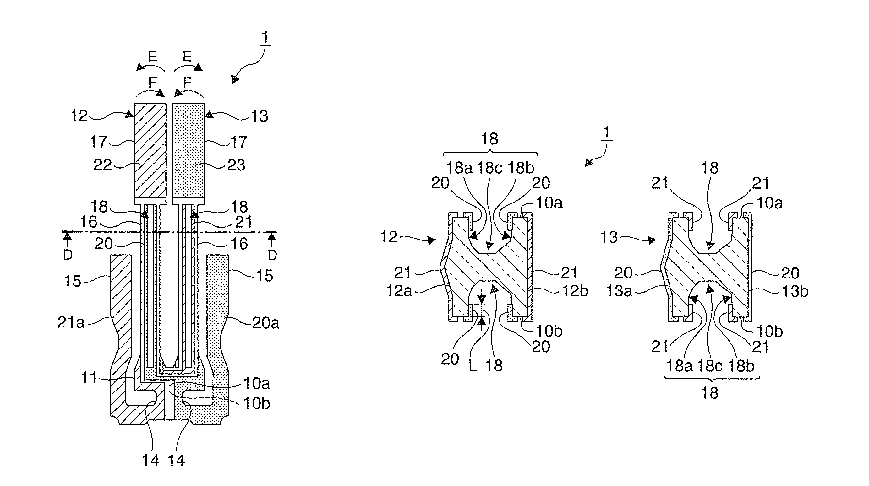
Figure 1 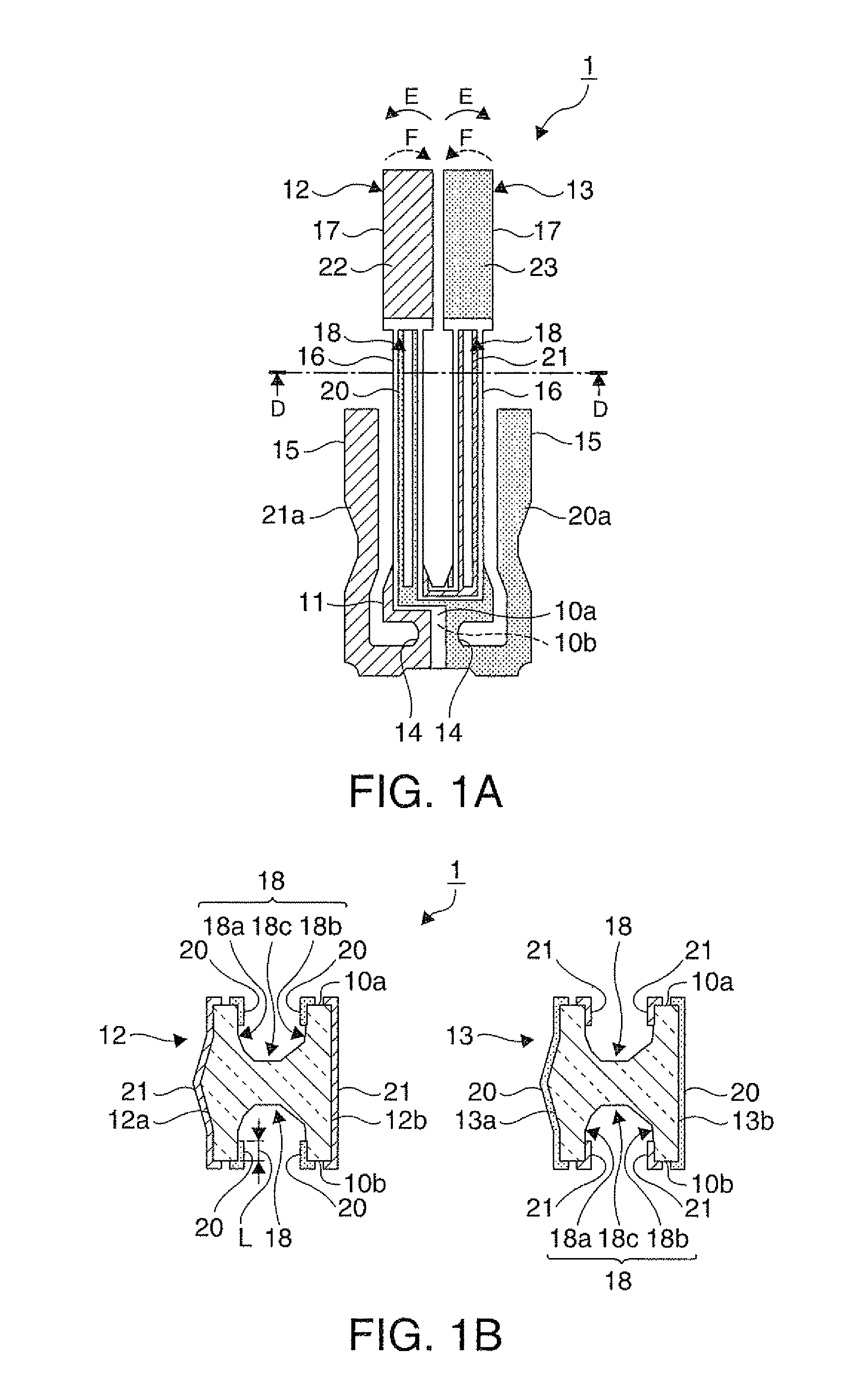
Figure 2 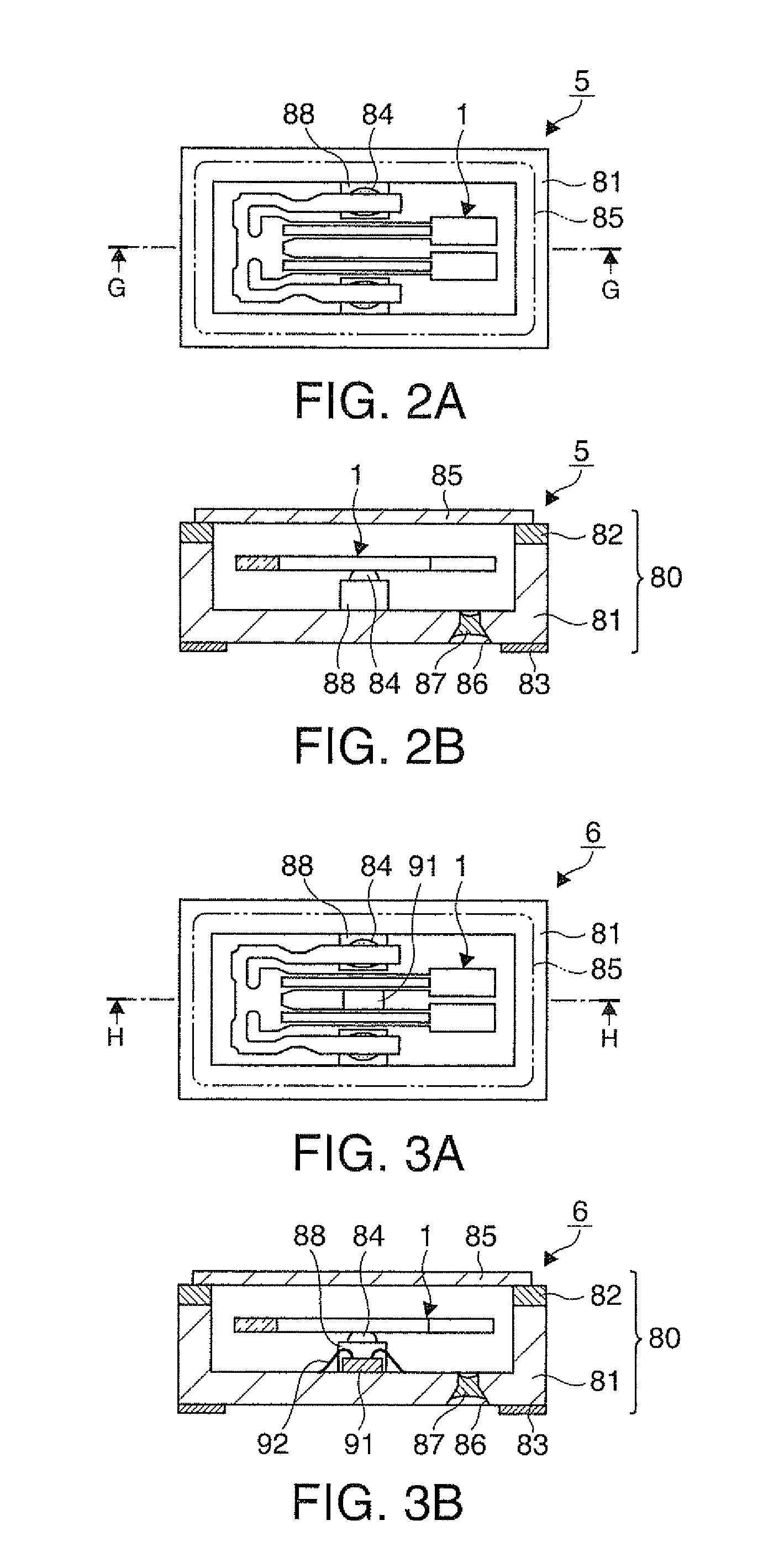
Figure 3
Abstract
Description
BACKGROUND
[0001] 1. Technical Field
[0002] The present invention relates to a resonator element, a resonator having the resonator element, and an oscillator having the resonator element.
[0003] 2. Related Art
[0004] In the related art, a tuning-fork type piezoelectric resonator element (hereinafter referred to as a resonator element) in which a pair of resonating arms alternately vibrates in the flexural vibration mode in the direction towards or away from each other is widely used as a resonator element.
[0005] A loss of vibration energy when such a resonator element vibrates in the flexural vibration mode leads to an increase of the CI (Crystal Impedance) value or a decrease of the Q value and thus causes deterioration of performances. Here, the CI value is a value which serves as an indicator of the likelihood of oscillation, and the lower it is, the more the resonator element is likely to oscillate. The Q value is a dimensionless number representing a vibration state, and the higher it i...
Examples
first embodiment
[0052]FIGS. 1A and 1B are schematic diagrams showing a simplified configuration of a resonator element according to a first embodiment, in which FIG. 1A is a planar diagram, and FIG. 1B is a cross-sectional diagram taken along the line D-D in FIG. 1A.
[0053]In FIG. 1A, hatching or shading is added to electrode parts for the sake of convenience, and the electrode parts are simplified or partially omitted for better understanding of the drawing.
[0054]As shown in FIGS. 1A and 1B, a crystal resonator element 1 used as a resonator element is a resonator element of which the outer shape is formed by wet-etching, using a photolithography technique, a wafer-shaped crystal substrate which is used as a base material and which is cut, for example, from crystal ore, at predetermined angles.
[0055]The crystal resonator element 1 includes a base portion 11, a pair of resonating arms 12 and 13 extending approximately in parallel from the base portion 11, a pair of notches 14 which is notched from bo...
second embodiment
[0096]Next, a resonator having the crystal resonator element described above will be described as a second embodiment.
[0097]FIGS. 2A and 2B are schematic diagrams showing a simplified configuration of a resonator according to the second embodiment, in which FIG. 2A is a planar diagram, and FIG. 2B is a cross-sectional diagram taken along the line G-G in FIG. 2A. The electrodes of the crystal resonator element are not illustrated for better understanding of the drawings.
[0098]As shown in FIGS. 2A and 2B, a crystal resonator 5 as a resonator includes the crystal resonator element 1 of the first embodiment and a package 80 that accommodates the crystal resonator element 1.
[0099]The package 80 includes a package base 81, a shim ring 82, a cover 85, and the like.
[0100]The package base 81 has a recess so that the crystal resonator element 1 can be accommodated therein, and connection pads 88 connected to the mount electrodes 20a and 21a (not shown; see FIGS. 1A and 1B) of the crystal reso...
third embodiment
[0107]Next, an oscillator having the crystal resonator element described above will be described as a third embodiment.
[0108]FIGS. 3A and 3B are schematic diagrams showing a simplified configuration of an oscillator according to the third embodiment, in which FIG. 3A is a planar diagram, and FIG. 3B is a cross-sectional diagram taken along the line H-H in FIG. 3A. The electrodes of the crystal resonator element are not illustrated for better understanding of the drawings.
[0109]A crystal oscillator 6 as an oscillation has configuration in which the crystal resonator 5 described above further includes a circuit element. The same portions as those of the crystal resonator 5 will be denoted by the same reference numerals, and description thereof is omitted.
[0110]As shown in FIGS. 3A and 3B, the crystal oscillator includes the crystal resonator element 1 of the first embodiment, an IC chip 91 as a circuit element having an oscillation circuit that oscillates the crystal resonator element...