
Process for preparing methanol from pyrolytic hydrogen
The described process addresses the inefficiencies and high carbon footprint of current methanol production by utilizing pyrolysis and hydrogenation to produce methanol with reduced hydrogen demand and lower operational costs, potentially achieving CO2 neutrality when using biogas.
Patent Information
- Application Number
- PCT/EP2024/077540
- Authority / Receiving Office
- WO · WO
- Patent Type
- Applications
- Current Assignee / Owner
- Priority Date
- 2023-10-06
- Filing Date
- 2024-10-01
- Publication Date
- 2025-04-10
AI Technical Summary
Current methanol production processes are resource-intensive and costly, with high hydrogen demand and significant carbon footprint, necessitating the development of more efficient and environmentally friendly methods.
A process involving pyrolysis and hydrogenation of a feed stream containing light hydrocarbons and optional carbon oxides and sulfur compounds to produce crude pyrolytic gases and solid carbon, followed by separation, conversion with carbon oxides to crude methanol, and recycling of hydrogen for enhanced efficiency.
This process reduces hydrogen demand, lowers operational costs, and decreases carbon footprint, achieving a more resource-conserving and efficient methanol production while potentially becoming CO2-neutral or CO2-negative when using biogas/biomethane as feedstock.
Smart Images
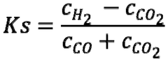
Figure IMGF000020_0001 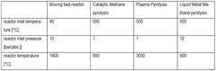
Figure IMGF000019_0001 
Figure IMGF000019_0002
Abstract
Description
[0001] Process for preparing methanol from pyrolytic hydrogen
[0002] Description
[0003] The present invention relates to a process for preparing methanol by
[0004] (a) Pyrolyzing and hydrogenating a feed stream (I) containing light hydrocarbons and optionally carbon oxides and sulfur compounds into (al) a crude pyrolytic gaseous product stream (III) containing hydrogen, residual methane, and optionally carbon oxides and hydrogen sulfide and into (ail) solid carbon (IV);
[0005] (b) Separating solid carbon (IV) from the crude pyrolytic gaseous product stream (III);
[0006] (c) Optionally separating hydrogen sulfide from the crude pyrolytic gaseous product stream (III) resulting in (ci) a raw pyrolytic gaseous product stream (VI) containing hydrogen, residual methane and optionally carbon oxides and (cii) optionally adsorbed sulfur (V);
[0007] (d) Converting said crude or raw pyrolytic gaseous product stream (III) or (VI) with carbon oxides (II) into crude methanol (VII);
[0008] (e) Separating uncondensed gas stream, purge gas (XII), from said crude methanol (VI I), thereby a methanol stream (VIII) is obtained;
[0009] (f) Purifying said methanol stream (VIII);
[0010] (g) Separating hydrogen (XIV) from said purge gas (XII);
[0011] (h) Recycling said hydrogen (XIV) to the methanol synthesis unit of stage (d).
[0012] Methanol (MeOH) produced with a low product carbon footprint (PCF) is required as an important synthesis raw material for the chemical industry, e.g. for the syntheses of formaldehyde, acetic acid, methyl tert-butyl ether, dimethyl terephthalate, methyl methacrylate and methylamines, as an important solvent and especially as an alternative fuel and energy vector in the challenge to reduce emission of greenhouse gases such as CO2.
[0013] Up to now, methanol is produced on the industrial scale from synthesis gas in a reactor in the presence of a methanol synthesis catalyst. The synthesis gas comprises mainly hydrogen and carbon monoxide and / or carbon dioxide, water and inert gases like methane, nitrogen or argon.
[0014] The hydrogen feedstock may in principle come from a wide variety of different sources. Examples include the supply of hydrogen from other production plants in which hydrogen is formed as a by-product, for example from steamcrackers or refineries, from the processing of synthesis gas, from the cracking of hydrocarbons or from the electrolysis of water.
[0015] Due to the global attention to hydrogen being the key element for the energy transformation, the demand on hydrogen will increase exponentially, especially the demand on CO2-low hydrogen. Thus, there is a strong need for re- source-conserving, more efficient processes using hydrogen as a chemical base educt. The synthesis gas which is used in the classical methanol synthesis is typically obtained from natural gas or other streams comprising hydrocarbons. Standard preparation processes are steam reforming, autothermal reforming, combinations thereof or partial oxidation.
[0016] The synthesis gas should be substantially free of metals, half-metals, phosphorus, halogen and sulfur compounds. The catalytic methanol process is very sensitive against sulfur impurities in the feed. Therefore, the feed gas needs desulfurization upfront to the methanol synthesis. Desulfurization is typically done in two steps: a) Conversion of all sulfur containing impurities to H2S via hydrogenation, b) Removal of H2S via gas scrubbing (e.g. via ZnO, CuZnO, Fe(OH)3, Zeolites, MOFs). In most chemical site, the pipeline natural gas is desulfurized upfront. These treatment steps can be expensive and imply loss of feedstock.
[0017] In hydrocarbon pyrolysis, mainly named methane pyrolysis, hydrogen is obtained from methane, which is usually to come from natural gas, synthetic methane, industrial off gas, e.g. cracker off gas, biogas / biomethane or sewage gas. In contrast to reformation, however, no gaseous carbon dioxide is produced, but solid, high-purity carbon as a byproduct. The simultaneous production of high-purity carbon has a positive effect on economic efficiency. Therefore, methane pyrolysis is considered a promising sustainable technology for future hydrogen production. However, up to now, commercial methane pyrolysis processes are rare.
[0018] The generic term methane pyrolysis covers a wide range of processes. The best known and most advanced of these are: Plasma pyrolysis, Metal melting / Metal salt melting, Moving bed process, Fluidized bed catalytic process and Partial combustion. These processes differ in the form of the energy used (thermal, electrical, etc.), the process conditions (temperature, pressure, etc.), the catalysts and / or auxiliary materials used, the process flow and the technical readiness level (TRL).
[0019] US5767165 describes a process for the production of methanol from natural gas comprising the thermal decomposition of methane and the subsequent reaction of the resulting hydrogen gas with carbon dioxide in a methanol synthesis. The thermal energy necessary for the decomposition is provided by the combustion of natural gas or hydrogen. No details are given to the needed purification steps of the natural or pyrolytic hydrogen.
[0020] EP2684842 describes the production of synthesis gas by (I) a hydrocarbon decomposition step in which hydrocarbons are decomposed to generate hydrogen and nanocarbon, the raw pyrolytic gas is purified by a pressure swing adsorption (PSA) and transferred to the synthesis gas mixing equipment; (II) a carbon dioxide reduction step in which some of the generated nanocarbons are reacted with carbon dioxide to produce carbon monoxide; and (ill) a mixing step in which the purified hydrogen and produced carbon monoxide are mixed at a predetermined ratio to obtain synthetic gas.
[0021] WO 2018 / 229729 also describes a combined gasification and catalytic decomposition for the production of hydrogen and synthesis gas from hydrocarbons. Gaseous C1 -s hydrocarbon stream contacts hydrocarbon decomposition catalyst under conditions suitable to produce a carbon coated decomposition catalyst and product stream that in- eludes at least 50 mol.-% H2. In some embodiments, the product stream is passed through a gas separation unit to produce a products stream having 100 mol.% H2. The carbon coated hydrocarbon decomposition catalyst is contacted with water under conditions sufficient to oxidize the carbon and generate synthesis gas stream and regenerated hydrocarbon decomposition catalyst. The synthesis gas stream is mixed with the hydrogen stream and optionally used to produce methanol.
[0022] WO 2013 / 4391 and WO 2014 / 95661 describe a process for producing synthesis gas by reacting natural gas, blast furnace gases, associated gases and / or biogases / biomethane and carbon dioxide in a reaction chamber in a bed of carbon-containing solids to give a gaseous product stream containing hydrogen and carbon monoxide, wherein said bed is guided through the reaction chamber as a moving bed. Such synthesis gas can be used as a feedstock for methanol production. No details are given to any purification step of the natural or pyrolytic hydrogen.
[0023] WO 91 / 05734 relates to a process for conversion of carbonaceous feedstock to particulate carbon and methanol which comprises (i) a hydropyrolysis of a carbonaceous material such as bituminous or lignite coal obtaining a methane-rich gas stream, (ii) a methane pyrolysis of said stream obtaining a hydrogen- and carbon monoxide rich stream, and (iii) a methanol conversion of said stream. After condensation of the raw methanol-rich stream, a residual gas stream, the purge gas, containing 40 to 90 % hydrogen, 0 to 40 % carbon monoxide, 10 to 30 % methane, 0 to 10 % carbon dioxide, 0 to 3 % methanol and 0 to 1 5 water is obtained. Most of said purge stream is recycled to the hydropyrolysis and the remainder of said purge is removed to avoid accumulation of inert constituents in said recycle stream. Optionally said remainder is combusted as needed to provide additional thermal energy.
[0024] Task
[0025] It is an object of the present invention to find a resource-conserving, more efficient process for preparing methanol. It is a further object of the present invention to find a methanol process that is resource-conserving, more efficient in view of hydrogen. It is a further object of the present invention to find a methanol process that is less expensive than the state of the art technology, e.g. smaller sizes of reactors, devices and equipment. It is a further object of the present invention to find a methanol process with a lower carbon-footprint than the state of the art. It is a further object of the present invention to retrofit an existing methanol process with a hydrogen feed with a low carbon footprint.
[0026] Invention
[0027] This task is solved by the present invention relating to a process for preparing methanol by
[0028] (a) Pyrolyzing and hydrogenating a feed stream (I) containing light hydrocarbons and optionally carbon oxides and sulfur compounds into (ai) a crude pyrolytic gaseous product stream (III) containing hydrogen, residual methane, and optionally carbon oxides and hydrogen sulfide and into (aii) solid carbon (IV);
[0029] (b) Separating solid carbon (IV) from the crude pyrolytic gaseous product stream (III);
[0030] (c) Optionally separating hydrogen sulfide from the crude pyrolytic gaseous product stream (III) resulting in (ci) a raw pyrolytic gaseous product stream (VI) containing hydrogen, residual methane and optionally carbon oxides and (cii) optionally adsorbed sulfur (V); (d) Converting said crude or raw pyrolytic gaseous product stream (III) or (VI) with carbon oxides (II) into crude methanol (VII);
[0031] (e) Separating uncondensed gas stream, purge gas (XII), from said crude methanol (VI I); thereby a methanol stream (VIII) is obtained;
[0032] (f) Purifying said methanol stream (VIII);
[0033] (g) Separating hydrogen (XIV) from said purge gas (XII);
[0034] (h) Recycling said hydrogen (XIV) to the methanol synthesis unit of stage (d).
[0035] Stage a)
[0036] In stage (a) a feed stream (I) containing light hydrocarbons and optionally carbon oxides and sulfur compounds is fed into a methane pyrolysis unit and pyrolyzed and hydrogenated into (ai) a crude pyrolytic gaseous product stream (III) containing hydrogen, residual methane and optionally carbon oxides and hydrogen sulfide and into (aii) solid carbon (IV). Preferably, the feed stream (I) containing light hydrocarbons, sulfur compounds and optionally carbon oxides is fed into a methane pyrolysis unit and pyrolyzed and hydrogenated into (ai) a crude pyrolytic gaseous product stream (III) containing hydrogen, residual methane, hydrogen sulfide optionally carbon oxides and into (aii) solid carbon (IV)
[0037] Educt feed stream
[0038] The feed stream (I) containing light hydrocarbons, preferably gaseous C2-C4 alkanes, even more preferably methane, is preferably natural gas, associated gas, industry off-gas and / or biogas / biomethane. Such feed streams typically comprise light hydrocarbons like methane, ethane, ethylene, propane, propylene and butane, carbon monoxide and carbon dioxide, inert gases like nitrogen, and sulfur components.
[0039] The natural gas, depending on the natural gas reservoir, typically has the following composition: 60% and 99% Vol.- % of methane, 1 to 15 Vol.-% of C2-C4 alkanes, up to 20 Vol.-% sulfur components and up to 30 Vol.-% inert gases, especially nitrogen. Depending on the pipeline specifications, up to 20 Vol.-% of hydrogen might be added to the natural gas.
[0040] The associated gas typically comprises methane, ethane, ethylene, propane, propylene and butane and having the following composition: from 75 to 85% by volume of methane, from 1 to 10% by volume of ethane, from 1 to 10% by volume of propane, from 1 to 10% by volume of butane, from 0.1 to 5% by volume of nitrogen, from 0.1 to 10 % by volume of sulfur compounds and from 0 to 1% by volume of carbon dioxide.
[0041] The biogas / biomethane typically has the following composition: from 50 to 75% by volume of methane, from 25 to 50% by volume of CO2, from 0 to 10 % by volume of sulfur compounds and from 0 to 10% by volume of N2.
[0042] Dependent on the composition of the feed stream (I), additional carbon oxides (II) might be needed for the methanol synthesis. The amount of carbon oxides (II) to be fed is found from the mass balance of the streams supplied to and removed from the methanol synthesis unit (C). The additional carbon oxides stream (II) can preferably be mixed with the feed stream (I) and / or fed into the methane pyrolysis unit (A) separately. The use of carbon dioxide plus hydrogen instead of synthesis gas has the benefit that carbon dioxide is often easily available as a by-product or waste. Carbon dioxide may, for example, easily come from sources such as fossil based power plants, steal processes, cement industry, chemical production complexes or direct air capture. Using carbon dioxide as carbon source, this methanol process can become CO2-neutral or even CO2-negative while using biogas / biomethane as feedstock.
[0043] The hydrocarbon pyrolysis process, preferably an non-metal-catalyzed methane pyrolysis, does not need upfront desulfurization. All sulfur containing impurities are converted / hydrogenated to hydrogen sulfide during the pyrolysis reaction without affecting the methane conversion. The hydrogen sulfide can preferably be removed via one-step gas scrubbing after the methane pyrolysis unit.
[0044] Thus, the common two step desulphurization is not needed in the inventive process; the first desulphurization step of hydrogenation can be included in the pyrolysis step.
[0045] Methane Pyrolysis Technologies
[0046] In the methane pyrolysis stage (a) methane is decomposed into solid carbon and hydrogen. The process of methane pyrolysis is also referred to as methane decomposition. The pyrolysis can be conducted in different ways known to the persons skilled in the art: catalytically or thermally, and with heat input via plasma, resistance heating, liquid metal processes or autothermal (see for example N. Muradov and T. Veziroglu: "Green” path from fossil-based to hydrogen economy: An overview of carbon-neutral technologies", International Journal Hydrogen Energy 33 (2008) 6804- 6839, H.F. Abbas and W.M.A. Wan Daud: Hydrogen production by methane decomposition: A review, International Journal Hydrogen Energy 35 (2010) 1160-1190), R. Dagle et al.: An Overview of Natural Gas Conversion Technol- gies for Co-Production of Hydrogen and Value-Added Solid Carbon Products, Report by Argonne National Laboratory and Pacific Northwest National Laboratory (ANL-17 / 11, PNNL-26726) November 2017).
[0047] Thus, the generic term methane pyrolysis covers a wide range of processes. The best known and most advanced of these are: Plasma pyrolysis, Metal melting / Metal salt melting, Moving bed process and Fluidized and fixed bed catalytic process. These processes differ in the form of the energy used (thermal, electrical, etc.), the process conditions (temperature, pressure, etc.), the catalysts and / or auxiliary materials used, the process flow etc.
[0048] The solid carbon type generated in the methane pyrolysis depends on the reaction conditions, reactor and heating technology. Examples are
[0049] - carbon black from plasma processes
[0050] - carbon powder from liquid metal processes
[0051] - granular carbon from thermal pyrolysis in fixed, moving or fluidized bed reactors.
[0052] Plasma Pyrolysis For plasma pyrolysis (see for example WO2015116797, WO2015116800), a plasma with >3000 °C is generated and mixed with ethane rich natural gas or ethane rich off-gas, which is pyrolyzed. The gas mixture leaves the reactor at temperatures between 1500 - 2000 °C. The reaction produces solid carbon in the form of carbon black which is discharged from the reactor with the gas and then separated. Various technologies such as arc, microwave and gas plasma technologies can be used for this purpose.
[0053] Partial Combustion process or pulsed reaction process
[0054] For a partial or pulsed combustion process, the heat for the thermal pyrolysis reaction is supplied by pulsed combustion (see for example WC2020118417 and US20220185664). Before a feedstock (containing hydrocarbon), is split into hydrogen and solid carbon in a combustion chamber, a combustible gas (containing hydrocarbons and oxidants) is pre-mixed in a mixing chamber. The reaction in the combustion chamber takes place when the gas mixture is heated up to 1350K and a pressure of over 20 bar is reached. Products leaving the reactor will be separated into gas and solid carbon for further processing.
[0055] Molten metal I molten metal salt
[0056] The pyrolysis processes using molten metals or molten metal salts (see for example W02020161192, WO2021183959) use the heat from the melt for pyrolysis. In addition, metals can be selected that have a catalytic effect, so that pyrolysis can take place at relatively low temperatures of approx. 800 - 1200 °C. The ethane rich natural gas or ethane rich off-gas is fed into the molten metal; the bubbles formed in the process rise upwards in the reactor, whereby the hydrocarbons decompose and form mainly methane, hydrogen and solid carbon. Depending on the process and the metals used, the carbon floats on the melt and is skimmed off or leaves the reactor together with the gas stream and is then separated. In both cases, the carbon is characterized by a very small particle size and bulk density. Due to adhesion of the melt to the carbon particles, purification of the carbon might be necessary for some processes and applications.
[0057] Catalytic process
[0058] Catalysts can also be used to reduce the high reaction temperatures (see for example WC2011029144, WC2016154666). For hydrocarbon pyrolysis a very cost-effective alternative is the use of iron oxide catalysts. Reaction temperatures of approx. 700 to 1000°C can be realized. In order to achieve the best possible heat and mass transfer, the reactions take place, for example, in the fluidized bed, with the catalyst as the fluidized material. The hydrocarbon is decomposed at the catalytic surface.
[0059] Fixed or Moving bed process
[0060] The hydrocarbon pyrolysis of stage (a) is conducted in a moving or fixed bed reactor, wherein the bed contains as substrates preferably carbon materials, metals, ceramics, and a mixture thereof, preferably at temperatures ranging from 500 to 2000°C, preferably ranging from 1000 to 1600°C, even more preferably ranging from 1200 to 1500°C, and at pressures ranging from 1 to 100 bar, preferably from 5 to 50 bar. The pyrolysis can either be realized as fixed bed, preferably in a cyclical operation mode, preferably including a production and a regeneration mode as described for example in WO 2018 / 083002, or in a moving bed as described for example in US 2982622, WO 2019 / 145279 and WO 2020 / 200522.
[0061] The pyrolysis process is preferably heated electrically, even more preferably by resistive heating (Joule heating) of the substrate material as described for example in US 2982622, WO 2019 / 145279 and WO 2020 / 200522.
[0062] Preferably the pyrolysis process is located at an existing chemical production site, especially at an existing methanol production site, or at gas wells.
[0063] Preferred Process Conditions: Moving Bed
[0064] Preferably the substrate is guided in form of a moving bed through the reaction chamber, with methane and / or other light hydrocarbons being passed advantageously in countercurrent to the substrate.
[0065] For this purpose, the reaction chamber is preferably rationally designed as a vertical reactor, which means that the movement of the moving bed is gravity driven. Flow through the moving bed is taking place, advantageously, homogeneously, and uniformly (see for example WO 2013 / 004398, WO 2019 / 145279 and WO 2020 / 200522). Methane and / or other light hydrocarbons are preferably introduced via the bottom of the reactor, preferably having a temperature of 10 to 200°C. The substrate is preferably introduced via the top of the reactor, preferably having a temperature of 10 to 200°C. Hydrogen is preferably taken off via the top of the reactor, preferably having a temperature of 10 to 200°C. The granular pyrolytic carbon produced preferably deposited on solid substrates and withdrawn with the substrates via the bottom of the reactor, preferably having a temperature of 10 to 200°C.
[0066] The discharged carbon is preferably at least partly recycled and introduced into the reactor again using it as substrate for the moving bed. As a result, a continuous process of the moving bed is achieved.
[0067] The flow velocity of the substrate is advantageously in the range of 0.005 to 0.5 cm / s. The flow velocity of the gas flow is advantageously in the range of 0.025 to 2 m / s.
[0068] The gas residence time in the reactor is advantageously between 0.5 and 50 s, preferably between 1 and 20 s. The residence time of the substrate is preferably between 0.5 and 15 hours, preferably between 1 and 10 hours and more preferably between 2 and 8 hours.
[0069] Substrate
[0070] The substrate can either be a fixed support / substrate in the reactor (a pre-installed part) or a granular sup- port / substrate material. The preferred substrate is a carbon-containing substrate, for example pyrolytic carbon itself. The particle size of a preferred substrate is in the range of 0.1 to 10 mm, preferably 0.3 to 8 mm. Preferably the substrates are carbonaceous materials that are macro-structured carbonaceous materials, wherein the porosity of the carbonaceous material is in the range of 30 to 70 vol.-% and the carbonaceous material contains of a carbon content of 98 wt.-% to 100 wt.-%, preferably 99 wt.-% to 100 wt.-%, even more preferably 99.5 wt.-% to 100 wt.-% and a content of alkaline-earth metals, transition metals and metalloids of 0 and 2 wt.-%, preferably 0 to 1 wt.-%, even more preferably 0 to 0.5 wt.-%, in relation to the total mass of solid carbonaceous material (see WO 2023 / 057242).
[0071] The BET surface area of the substrate is preferably between 0.1 and 100 m2 / g, preferably 0.1 and 50 m2 / g, in particular 0.1 to 30 m2 / g.
[0072] Preferably, the real density of the substrate is in the range of 1 .5 to 2.5 g / cc (real density in xylene, ISO 8004). Preferably, the bulk density of the substrate is in the range of 0.5 to 1 .5 g / cc.
[0073] Pyrolytic granular carbon (IV)
[0074] Typically, the real density of the granular pyrolytic carbon (IV) produced via the described methane pyrolysis process of stage (a) two is in the range of 1 .5 to 2.5 g / cc, preferably 2.0 to 2.3 g / cc (real density in xylene, ISO 8004). Typically, the bulk density of the granular pyrolytic carbon (IV) is in the range of 0.5 to 1 .5 g / cc, more preferably 0.7 to 1 .3 g / cc.
[0075] Typically, the ash content of the granular pyrolytic carbon (IV) composition is in the range of 0.001 to 1 weight-% of the composition, preferably 0.01 to 0.2 weight-%.
[0076] Typically, the carbon content of the granular pyrolytic carbon (IV) composition is in the range of 98 to 100 weight-%, more preferably 99.5 to 100 weight-%, even more 99.75 to 100 weight-%, even more 99.9 to 100 weight-%.
[0077] Typically, the impurities of the granular pyrolytic carbon (IV) are: S in the range of 0 to 0.5 weight-%, more preferably 0 to 0.1 weight-%, Fe in the range of 0 to 1000 ppm, preferably 0 to 500 ppm, Ni in the range of 0 to 250 ppm, preferably 0 to 100 ppm, V in the range of 0 to 250 ppm, more preferably 0 to 100 ppm. Na in the range of 0 to 200 ppm, preferably 0 to 100 ppm. Oxygen is in the range of 0 to 100 ppm, preferably below the detection limit.
[0078] Typically, 95 weight-% of the carbon of the granular pyrolytic carbon (IV) is not-functionalized, preferably 98 weight- %, wherein carbon functionalization refers to a reaction in which a carbon-carbon bond is broken and replaced by a carbon-X bond (where X is usually hydrogen, oxygen, sulfur, phosphorus, nitrogen, halogens, and / or metals).
[0079] Typically, the cation exchange capacity (CEC) of granular pyrolytic carbon (IV) is about 0.01 to 1 .5 cmol / kg, preferably 0.025 to 0.75 cmol / kg. Typically, the particle size of the granular pyrolytic carbon (IV) directly resulting of the pyrolysis of gaseous hydrocarbons - without any agglomeration step - is in the range of 0.3 mm (d10) to 8 mm (d90), preferably 0.5 mm (d10) to 5 mm (d90), more preferably 1 mm (d10) to 4 mm (d90).
[0080] Typically, the porosity of the granular pyrolytic carbon (IV) is between 0% to 15%, preferably 0.2% to 10%, most preferably 0.2% to 5% (Hg porosimetry, DIN66133).
[0081] Typically, the specific surface area of the granular pyrolytic carbon (IV) measured by Hg porosimetry (DIN66133) is in the range of 0.001 to 10 m2 / g, preferably 0.001 to 5 m2 / g, even more preferably 0.05 to 2 m2 / g.
[0082] Preferred Reactor
[0083] Preferably, the reactor of the methane pyrolysis unit (A) for carrying out the methane pyrolysis, in which hydrogen
[0084] (III) and granular pyrolytic carbon (IV) are produced from hydrocarbons, preferably methane, comprises:
[0085] - a reactor surrounding a reactor interior
[0086] - the reactor is configured to provide a gravity-driven moving bed in a reaction zone of the reactor interior, which gravity-driven moving bed comprises a large number plurality of solid substrates, wherein the reactor is also configured to guide methane into the reaction zone, wherein, in order to heat methane, the reactor is configured to heat the solid substrates in the reaction zone by generating an electric current in the solid substrates between a pair of first and second electrodes such that, by transferring heat from the solid substrates to methane,
[0087] - methane in the reaction zone can be heated to a reaction temperature to produce hydrogen and granular pyrolytic carbon,
[0088] - and wherein the reactor interior also comprises a first heat integration zone in which heat from hydrogen produced in the reaction zone can be transferred to solid substrates of the reactor gravity driven moving bed which are to be guided into the reaction zone, and wherein the reactor interior also comprises a second heat integration zone in which heat from solid substrates of the reactor gravity driven moving bed coming from the reaction zone can be transferred to methane in order to preheat methane, wherein said reaction zone is arranged between said pair of first and second electrodes and said first heat integration zone is arranged above said first electrode and said second heat integration zone is arranged below said second electrode.
[0089] Preferably, the electrodes comprise a grid or are formed by a grid.
[0090] Preferred Moving Bed Method
[0091] Preferably a moving bed technology is used for the methane pyrolysis in the stage (a) comprising:
[0092] - a plurality of solid substrates (XVIII) is guided into the first heat integration zone and from there into the reaction zone,
[0093] - the solid substrates are heated in the reaction zone, - the solid substrates are guided from the reaction zone into the second heat integration zone and are withdrawn from the second heat integration zone,
[0094] - methane (I) is introduced into the second heat integration zone and from there into the reaction zone, wherein methane in the second heat integration zone is heated against solid substrates coming from the reaction zone, wherein the solid substrates are cooled, and wherein the methane is contacted with the heated solid substrates in the reaction zone, wherein heat from the heated solid substrates is transferred to methane in order to heat methane in the reaction zone, wherein methane is decomposed to hydrogen and granular pyrolytic carbon in the reaction zone,
[0095] - hydrogen produced is guided from the reaction zone into the first heat integration zone, wherein the solid substrates in the first heat integration zone are preheated against hydrogen coming from the reaction zone, wherein hydrogen is cooled, and wherein
[0096] - hydrogen is withdrawn (III) from the first heat integration zone
[0097] - granular pyrolytic carbon produced (IV) is deposited on solid substrates and withdrawn with the substrates
[0098] - withdrawn substrate is preferably at least partly processed, recycled and introduced into the reactor
[0099] - withdrawn hydrogen is preferably at least partly recycled and introduced into the reactor.
[0100] Stage (b): Separating solid carbon (IV)
[0101] The separation of solid carbon (IV) depends on the chosen pyrolysis technology and is known by the skilled person in the art.
[0102] As mentioned above, for example, in a plasma pyrolysis the solid carbon in the form of carbon black is discharged from the reactor with the gas and then separated, e.g. by a cyclone. The solid carbon might be post-treated, e.g. agglomerated. Depending on the process and the metals used in molten metal pyrolysis, the carbon floats on the melt and is skimmed off or leaves the reactor together with the gas stream and is then separated, e.g. filter / cyclone. In addition, a purification step to remove residual metal from the carbon could be required e.g. washing, evaporation. In the catalytic pyrolysis technology and in the fixed and moving bed technology, the solid carbon is deposited on the surface of the catalyst and / or support / substrate and taken off the reactor via the catalyst and / or support / substrate.
[0103] Crude pyrolytic gaseous product stream (III)
[0104] The crude pyrolytic gaseous product stream contains hydrogen, residual methane and optionally carbon oxides and hydrogen sulfide depending on the hydrocarbon feed used. Typically, the crude pyrolytic gaseous product stream has the following composition: 10 Vol-% to 98 Vol.-% of hydrogen, preferably 20 to 95 vol.-% of hydrogen, most preferably 50 to 95 vol. % of hydrogen, 0.1 to 30 Vol.-% methane, up to 10 Vol.-% hydrogen sulfide and up to 30 Vol.-% inert gases, especially nitrogen. If biogas / biomethane is used as hydrocarbon feed or carbon oxides are added to the hydrocarbon feed, the crude pyrolytic gaseous product stream also contains carbon oxides, preferably 20 to 50 Vol.- % of carbon oxides.
[0105] Stage c: Separating gaseous hydrogen sulfide The hydrogen sulfide can preferably be removed from the crude gaseous product stream via gas cleaning / scrubbing, e.g. via ZnO, CuZnO, Fe(OH)3, Zeolites, MOFs, as known in the state of the art. Typical process conditions of the gas cleaning are 60 to 180°C and 1 to 100 bar.
[0106] If a gas compressor is needed before the methanol synthesis, the gas cleaning is preferably embedded in the compressor unit. Preferably, the inlet temperature of the absorber bed can be provided by the heat of compression between the compressor stages.
[0107] Stage d: Converting raw gaseous product stream (III) or (VI) into crude methanol stream (VII)
[0108] The raw pyrolytic gaseous product stream (III) or (VI) is mixed with a hydrogen recycle (XIV), described further down in connection with stage h, and fed into a methanol synthesis unit (C).
[0109] Optionally, other carbon oxide streams (II) can be added to the raw pyrolytic gaseous product stream (VI). The amount of carbon oxide streams (II) to be added is found from the mass balance of the streams supplied to and removed from the methanol synthesis unit (C).
[0110] The conversion of carbon oxide and hydrogen to methanol is conducted preferably at a temperature of 150 to 300°C and a pressure of 3 to 10 MPa abs in the presence of a methanol synthesis catalyst (see for example Ullmann's Encyclopedia of Industrial Chemistry, "Methanol” chapter, 2012 Wiley-VCH Verlag GmbH & Co. KGaA, Weinheim, Germany or WO 2021 / 148262, especially pages 8 to 10 of).
[0111] The complex reaction mixture (VII), the crude methanol stream, typically contains methanol, water, dimethyl ether, carbon monoxide, carbon dioxide, hydrogen and methane.
[0112] Stage e: Separating uncondensed gas stream, purge gas, from said crude methanol
[0113] For separation of the methanol (VIII), this crude methanol stream is typically first condensed out in the methanol separation unit (D) resulting in a purge feed stream (XII) and a degassed methanol stream (VIII).
[0114] The uncondensed gas stream (XII) especially comprises the unconverted carbon dioxide, carbon monoxide and hydrogen feedstocks, and methane.
[0115] Preferably, a portion of the uncondensed gas stream (XII) is recycled into the methanol synthesis unit as recycle gas (XV). This recycle increases exploitation of the carbon oxide and hydrogen containing feedstocks.
[0116] Stage f: Purifying said methanol
[0117] In stage (f) of the process of the invention, the degassed methanol stream (VIII) obtained in stage (e) is separated by distillation in a methanol purification unit (E) into a low boiler stream (XI) comprising carbon dioxide and dimethyl ether, into methanol (IX) and into a high boiler stream (X) comprising water and also further components that are higher-boiling than methanol, for example acetic acid, higher alcohols, higher esters, higher ethers or paraffins.
[0118] Stage g: Separating hydrogen from said purge gas
[0119] In stage (g) hydrogen (XIV) is separated from the purge gas (XII) in a hydrogen recovery unit (F).
[0120] In principle, the hydrogen can be removed from the purge gas (XII) using any apparatus suitable for separating hydrogen from a gas stream comprising carbon dioxide, carbon monoxide, hydrogen and methane. Corresponding apparatuses are common knowledge to the person skilled in the art, for example pressure swing adsorption or permeation.
[0121] Typically, said separated hydrogen stream (XIV) generally has a relatively high purity. The preferred pressure swing adsorption affords the hydrogen separated off generally in a purity of 90% to 100 vol.-%, preferably of > 95 vol.-%, more preferably of > 99 vol.-% and most preferably of > 99.5 vol.-%.
[0122] Optionally: combustion and CO2 recovery (see Fig. 3-6)
[0123] The off gas stream (XIII) from the hydrogen recovery unit (F) is preferably fed into a combustion unit (G) and combusted therein with supply of an oxygenous gas (XX) having a preferred oxygen content of 30% to 100 vol.-%, forming a carbon dioxide-containing flue gas (XVI).
[0124] Since the methane and dimethyl ether components of value in the off-gas stream (XIII), but also other carbon- containing by-products present therein, cannot be used directly in this form as reactants for the methanol synthesis, it is necessary first to convert them chemically to a suitable form. Therefore, it is preferred to combust these in a combustion unit (G) to form a carbon dioxide-containing flue gas (XVI). The conversion to carbon dioxide makes it possible also to reuse the components of value methane, dimethyl ether and further carbon-containing by-products as reactant in the methanol synthesis.
[0125] In general, the carbon dioxide-containing flue gas (XVI) discharged from the combustion unit (G) has a carbon dioxide content of 25% to 90 vol.-%, preferably > 70 vol .-%, and more preferably < 80 vol.-%.
[0126] Preferably, the combustion unit (G) comprises beside a combustion chamber also a condenser in which water is condensed out of the combustion gas and conducted away as stream (XXI).
[0127] Preferably, all three off-gas streams, off-gas (XI) from the methanol purification unit (E), off-gas (XIII) from the hydrogen recovery unit (F) and off-gas (XIX) from the carbon processing unit (J) are guided to combustion unit (G).
[0128] The carbon dioxide-enriched stream (XVII) is then preferably separated from the carbon dioxide-containing flue gas (XVI) in a carbon dioxide recovery unit (H) forming an off-gas stream (XXII), preferably containing condensed water. Corresponding apparatuses and processes are known to those skilled in the art. A general overview of possible apparatuses and processes can be found, for example, in Ullmann's Encyclopedia of Industrial Chemistry, "Carbon Dioxide” chapter, Section 13.3 "CCS-related Separation Technologies", 2014 Wiley-VCH Verlag GmbH & Co. KGaA, Weinheim, Germany.
[0129] The carbon dioxide-enriched stream (XVII) separated off in the carbon dioxide recovery unit (H) is preferably subsequently recycled to the methanol synthesis unit (C) of stage (d), for example, by introducing said separated carbon dioxide-enriched stream (XVII) to the raw pyrolytic gaseous product stream (VI).
[0130] Stage h: Recycling said hydrogen (XIV) to the methanol synthesis unit (C) of stage (d)
[0131] The separated hydrogen stream (XIV) from the hydrogen recovery unit (F) is recycled to the methanol synthesis unit (C) of stage (d) by, for example, introducing said separated hydrogen stream (XIV) to the raw pyrolytic gaseous product stream (VI).
[0132] Use of methanol
[0133] The obtained methanol can be used for fuel applications, such as the production of MTBE I TAME, gasoline blending, the production of dimethyl ether and the production of biodiesel, for producing formaldehyde, acetic acid, olefins, sodium methylate, methylation products, such as dimethylphenol, for the production of dimethy Iterephthalat and methyl mercaptane.
[0134] The formaldehyde obtained from the methanol of the invention can be further used e. g. for the production of polyoxymethylene, butinediol, methylendiphenyldiisocyanate, neopentylglycol, methacrylic acid, phenol formaldehyde resins, urea condensation resins, melamine resins and acetone resins.
[0135] The acetic acid obtained from the methanol of the invention can be further used e. g. for the production of chloroacetic acid, acetic acid esters, methylisopropylketone and acetic acid anhydride.
[0136] The methyl mercaptane obtained from the methanol of the invention can be further used e. g. for the production of methylmercaptopropionaldehyde, dimethyldisulfide and methanesulfonic acid.
[0137] Advantages of the present invention
[0138] The advantage of the present invention is the lowered H2-demand of the methanol synthesis resulting in a resourceconserving, more efficient methanol process. In addition, the dimension of the hydrogen recovery unit (F) can be reduced resulting in less OPEX and CAPEX-costs. Furthermore, the desulfurization can be integrated in the combined methane pyrolysis and methanol process saving the hydrogenation and desulfurization step of the hydrocarbon feed to the methane pyrolysis. With an additional combustion step a CO2-free process is possible resp. by using biogas / biomethane the process is also carbon negative. Figures
[0139] Fig 1 shows the block diagram of a general embodiment of the process of the invention.
[0140] Fig 2 shows a block diagram of a general embodiment in which a portion of the uncondensed gas stream (XII) is recycled into the methanol synthesis unit as recycle gas (XV).
[0141] Fig 2a shows the inventive example 1 and 3 as described under the section Examples.
[0142] Fig 3 shows a block diagram of a general embodiment in which the off gas (XIII) from the hydrogen recovery unit (F) is combusted forming carbon dioxide-containing flue gas (XVI), and a carbon dioxide-enriched stream (XVII) is separated from the carbon dioxide-containing flue gas (XVI) in a carbon dioxide recovery unit (H) and is recycled to the methanol synthesis unit (C).
[0143] Fig 3a shows the inventive example 2 and 4 as described under the section Examples.
[0144] Fig 4 shows the comparative example 1 and 2 as described under the section Examples.
[0145] Fig 5 shows a block diagram of a general embodiment in which part of the solid carbon are recycled to the pyrolysis unit.
[0146] Fig 6 shows a block diagram of a general embodiment in which all three off-gas streams, off-gas (XI) from the methanol purification unit (E), off-gas (XIII) from the hydrogen recovery unit (F) and off-gas (XIX) from the carbon processing unit (J) are guided to combustion unit (G).
[0147] The labels in the Figures have the following meanings:
[0148] A Hydrocarbon pyrolysis unit
[0149] B Desulfurization unit
[0150] C Methanol synthesis unit
[0151] D Methanol separation unit
[0152] E Methanol purification unit
[0153] F Hydrogen recovery unit
[0154] G Combustion unit
[0155] H Carbon oxide recovery unit
[0156] J Carbon processing unit
[0157] I Hydrocarbons containing stream
[0158] II Carbon oxide containing stream
[0159] III Crude pyrolytic gaseous product stream
[0160] IV Solid carbon
[0161] V Sulfur
[0162] VI Raw pyrolytic gaseous product stream, make-up gas stream
[0163] VII Crude methanol stream
[0164] VIII Degassed methanol stream.
[0165] IX Methanol
[0166] X Water and high boiler stream XI Off-gas stream, low boiler stream from methanol distillation
[0167] XII Purge gas stream comprising carbon dioxide, carbon monoxide, hydrogen and methane
[0168] XIII Off-gas stream from hydrogen recovery
[0169] XIV Hydrogen stream from recovery
[0170] XV Carbon oxide containing stream
[0171] XVI Recycle gas stream containing carbon dioxide, carbon monoxide, hydrogen and methane
[0172] XVII Recycle gas stream containing a carbon dioxide-enriched stream
[0173] XVIII Carbon support / substrate recycle
[0174] XIX Carbon processing off-gas
[0175] XX Oxygenous gas
[0176] XXI Water stream from combustion unit including a condenser
[0177] XXII Off-gas stream from carbon dioxide recovery unit
[0178] Process description
[0179] The process conditions of the single units are given in the examples.
[0180] Fig. 2 / Fig 2a (Inventive example):
[0181] Natural gas (I) is fed into a methane pyrolysis unit (A) and pyrolyzed into a crude H2 stream (III) and solid carbon (IV). The crude H2 stream (III) coming from the methane pyrolysis section (A) is hydrotreated and desulfurized in the desulfurization section (B). Preferably the desulfurization section (B) is located in between 2 compressor stages of the compressor needed to achieve the desired pressure for the methanol synthesis. The inlet temperature of the reactor of the desulfurization section is adjusted at the outlet of the compressor stage and the fixed bed catalytic absorber. In the reactor all double and triple bonds components are hydrogenated to the paraffins and the H2S is absorbed in the copper phase of the catalytic absorber material. At the outlet of the reactor the inlet temperature of the next compressor stage is adjusted. The state-of-the-art methanol synthesis loop is operated with a water-cooled fixed bed reactor (C) and recycle gas (XV).
[0182] The crude methanol water mixture (VI I) is separated in the raw methanol separation section (VIII) by cooling down and condensation. The vapor phase part is the recycle gas stream (XV) and the purge-gas stream (XII).
[0183] To keep the ratio of make-up gas (VI) an recycle gas (XV) and so for the GHSV (Gas hourly space velocity) over the methanol synthesis catalyst and the inert components concentration, the synthesis loop is operated with a purge gas stream (XII). From this purge gas stream (XII) H2 is recovered by the hydrogen recovery section (F). The hydrogen recovery section (F) may be for example pressure swing absorption unit, membrane process or cold box. The recovered H2 is sent back to the methanol synthesis loop.
[0184] The make-up gas stream (VI) is a mixture of crude H2 from methane pyrolysis (A) and desulfurization section (B), the recovered H2 from hydrogen recovery unit (F), CO and / or CO2 (II). This make up gas stream (VI) is the feed stream of the methanol synthesis loop before mixing with the recycle gas stream (XV). In the state-of-the-art methanol purification section (E) the crude methanol water mixture is depressurized form methanol synthesis loop pressure down to lower 10 bar(abs.) and fractionated to off-gas stream (XI), pure methanol stream (IX) and water and high boilers stream (X).
[0185] Fig. 3 / Fig. 3a (Inventive example, CO2 emission free concept)
[0186] Natural gas (I) is fed into a methane pyrolysis unit (A) and pyrolyzed into a crude H2 stream (III) and solid carbon (IV). The crude H2 stream (III) coming from the methane pyrolysis section (A) is hydrotreated an desulfurized in the desulfurization section (B). Preferably the desulfurization section (B) is located in between 2 compressor stages of the compressor needed to achieve the desired pressure for the methanol synthesis. The inlet temperature of the reactor of the desulfurization section is adjusted at the outlet of the compressor stage and the fixed bed catalytic absorber. In the reactor all double and triple bonds components are hydrogenated to the paraffins and the H2S is absorbed in the copper phase of the catalytic absorber material. At the outlet of the reactor the inlet temperature of the next compressor stage is adjusted. The state-of-the-art methanol synthesis loop is operated with a water-cooled fixed bed reactor (C) and recycle gas (XV).
[0187] The crude methanol water mixture (VI I) is separated in the raw methanol separation section (VIII) by cooling down and condensation. The vapor phase part is the recycle gas stream (XV) and the purge-gas stream (XII).
[0188] To keep the ratio of make-up gas (VI) an recycle gas (XV) and so for the GHSV over the methanol synthesis catalyst and the inert components concentration, the synthesis loop is operated with a purge gas stream (XII). From this purge gas stream (XII) H2 is recovered by the hydrogen recovery section (F). The hydrogen recovery section (F) may be for example pressure swing absorption unit, membrane process or cold box. The recovered H2 is sent back to the methanol synthesis loop.
[0189] In the state-of-the-art methanol purification section (E) the crude methanol water mixture is depressurized form methanol synthesis loop pressure down to lower 10 bar(abs.) and fractionated to off-gas stream (XI), pure methanol stream (IX) and water and high boilers stream (X).
[0190] The off-gas stream (XIII) of the hydrogen recovery section (F) is mixed with the off-gas stream (XI) of the methanol purification section (E) and sent to the combustion (OxyFuel) section (G).
[0191] In the combustion (OxyFuel) (G) section the combined off-gases are burned with pure 02 to a CO2 rich flue gas.
[0192] The CO2 from the flue gas (XVI) is separated in the CO2 recovery unit (H) and recycled back to the methanol synthesis loop. The off-gas (XXII) is vented to atmosphere and contains the inert components like N2.
[0193] The make-up gas stream (VI) is a mixture of crude H2 from methane pyrolysis (A) after desulfurization section (B), the recovered H2 from hydrogen recovery unit (F), CO and the recycled CO2 (XVII) from the CO2 recovery unit (H). This make up gas stream (VI) is the feed stream of the methanol synthesis loop before mixing with the recycle gas stream (XV).
[0194] Fig. 4 (Comparative example) The first process step is the upfront desulfurization (B) of the natural gas (I). In the hydrogenation reactor all double and triple bonds components are hydrogenated to the paraffins and the sulfur containing components to H2S with for example a C0M0, NIMo catalyst on AI2O3. The H2S built, is absorbed on a ZnO absorber material. The desulfurized natural gas (la) is fed into a methane pyrolysis unit (A) and pyrolyzed into a crude H2 stream (III') and solid carbon (IV). The crude H2 stream (III') is purified in the hydrogen recovery section (F). The hydrogen recovery section (F) may be for example pressure swing absorption unit, membrane process or cold box.
[0195] The feed stream for the methanol unit is a make-up gas stream (VI) being a mixture of crude H2 stream (III') with CO and / or CO2 (II). This make up gas stream (VI) is mixing with the recycle gas stream (XV).
[0196] The state-of-the-art methanol synthesis loop is operated with a water-cooled fixed bed reactor (C) and recycle gas (XV).
[0197] The crude methanol water mixture is separated in the raw methanol separation section (VIII) by cooling down and condensation. The vapor phase part is the recycle gas stream (XV) and the purge-gas stream (XII).
[0198] To keep the ratio of make-up gas (VI) an recycle gas (XV) and so for the GHSV over the methanol synthesis catalyst and the inert components concentration, the synthesis loop is operated with a minimum purge gas stream (XII).
[0199] In the state-of-the-art methanol purification section (E) the crude methanol water mixture is depressurized form methanol synthesis loop pressure down to lower 10 bar(abs.) and fractionated to off-gas stream (XI), pure methanol stream (IX) and water and high boilers stream (X).
[0200] Examples:
[0201] Methods for the preparation of methanol from pyrolytic hydrogen, CO and CO2 were simulated using ASPEN PlusTM V11 simulation software in combination with a kinetic model to calculate the conversion of CO and 002 in the methanol synthesis reactor.
[0202] The general conditions of the methane pyrolysis are shown in T able 1 :
[0203] For the inventive and comparative examples, the parameters for the moving bed reactor are taken. The general conditions for the methanol synthesis are shown in Table 1
[0204] Tablet
[0205] For the inventive and comparative examples, these parameters for the methanol synthesis are kept unchanged. For the methanol synthesis a commercial state of the art methanol catalyst based on Cu / ZnO / AhOs is used. For the examples making methanol from H2, CO and CO2 the reactor inlet temperature is 193°C but for the examples making methanol from H2, and mainly CO2 a reactor inlet temperature of 220°C is used.
[0206] The catalyst is cooled by boiling water with a temperature of 212°C for making methanol from H2, CO and CO2 and 240°C for making methanol from H2, and mainly CO2. In all cases the reactor inlet pressure is 73 bar(abs.). The concentration of inert components at the methanol synthesis reactor is 30 vol-% for all inventive examples using crude H2. For the comparative examples with a feed of purified H2 the concentration of inert components at the methanol synthesis reactor is < 2.0 vol-%. The inert components are N2, CH4 and C2H6. The gas hourly space velocity (GHSV Nm3 / (m3Kat*h)) is kept constant with 6127 1 / h.
[0207] The stoichiometric constant Ks for all examples is 3.4 .
[0208] To adjust the GHSV together with the level of inert components an adequate amount of the recycle gas is removed and purged out of the methanol synthesis loop. The H2 yield of the H2 recovery section is in all examples 83%. The CH4 slip through the H2 recovery section is a 0.1 %.
[0209] Working example
[0210] In the following examples: after a whole number there is a comma, thousands are separated by a point. 1stExample (inventive)
[0211] The chosen compositions for the streams III, VI, XII, XIV, XIII and Xl+X are summarized in table 3. The inventive example 1 revers to Fig. 2a. Table 3:
[0212] In the inventive example 1 the methanol synthesis is operated with the reactive components mixture of H2, CO and CO2.
[0213] The crude H2 (stream III) is desulfurized at a Cu / ZnO catalytic absorber. The H2S builds very stable NiS, hence the sulfur concentration after the Cu / ZnO catalytic absorber is lower than 0.1 vol. ppm. Such a low sulfur content in the synthesis-gas is beneficial for the activity and lifetime of the methanol synthesis catalyst. To prepare an appropriate make-up gas (stream VI) for the methanol synthesis the desulfurized crude H2 and the H2 from H2 recovery unit are mixed. This mixture is enriched in CO2 and CO for a CO2 concentration of 3.5 vol.-% and a CO concentration of 26.7 vol.-%. The required stoichiometric constant Ks of the make-up gas stream (VI) is 2.050 to ensure a Ks of 3.4 before the methanol synthesis reactor.
[0214] Under these conditions, to keep the inert content level and the GHSV, the 233 Nm3 / tMeOH purge-gas stream (XII) with a H2 content of 50.5 vol.% is withdrawn from the methanol synthesis loop and fed to the H2 recovery section. From this stream 97 Nm3 / tMeoH nearly pure H2 with a H2 content of 99.9 vol.-% is recovered and sent back to the inlet of the methanol synthesis loop to the make-up gas stream.
[0215] The off-gas of the H2 recovery section together with the off-gases of the methanol purification section are sent to thermal used by combustion.
[0216] The next table 4 and 5 shows the compilation of the most important results for all inventive and comparative examples:
[0217] Table 4:
[0218] Table 5:
[0219] The carbon yield is 87.1% and the crude bfe-demand is 1595 Nm3 / tMeoH. Caused by the combustion of all off-gases, the CO2 emissions are 0.200 tco2 1 IMSOH.
[0220] The carbon yield is the ratio of all carbon fed to the process, including inert components like CH4, and C2H4 and the carbon in the valued product methanol. 2nd Example (inventive)
[0221] The chosen compositions for the streams III, VI, XII, XIV, XIII and Xl+X are summarized in table 6. The inventive example 2 revers to Fig. 3a. Table 6:
[0222] In the inventive example 2 the methanol synthesis is operated with the reactive components mixture of H2, CO and CO2 but without CO2 emission.
[0223] The crude H2 (stream III) is desulfurized at a Cu / ZnO catalytic absorber. The H2S builds very stable NIS, hence the sulfur concentration after the Cu / ZnO catalytic absorber is lower than 0.1 vol. ppm. Such a low sulfur content in the synthesis-gas is beneficial for the activity and lifetime of the methanol synthesis catalyst. To prepare an appropriate make-up gas (stream VI) for the methanol synthesis the desulfurized crude H2 and the H2 from H2 recovery unit are mixed. This mixture is enriched in CO for a CO concentration of 25.6 vol.-%. The CO2 generated by the OxyFuel combustion and CO2 recovery section is quantitatively reused for the methanol synthesis. The CO2 content in the make-up gas stream (VI) is 4.4 vol.-% and marginally higher than in the 1stinventive example with 3.5 vol.-%. The required stoichiometric constant Ks of the make-up gas stream (VI) is 2.047 to ensure a Ks of 3.4 before the methanol synthesis reactor.
[0224] Under these conditions, to keep the inert content level and the GHSV, the 242 Nm3 / tMeOH purge-gas stream (XII) with a H2 content of 50.9 vol.% is withdrawn from the methanol synthesis loop and fed to the H2 recovery section. From this stream 102 Nm3 / tMeOH nearly pure H2 with a H2 content of 99.9 vol.-% is recovered and sent back to the inlet of the methanol synthesis loop to the make-up gas stream.
[0225] The off-gas of the H2 recovery section together with the off-gases of the methanol purification section are sent to the OxyFuel combustion section. From the flue-gas of the OxyFuel combustion section the 107 Nm3 / tMeoH CO2 is recovered and sent back to the methanol synthesis loop and mixed in the in the make-up gas stream VI. The carbon yield (table 3) is 100% and the crude Fh-demand is 1617 Nm3 / tMeOH. This slightly higher than in the 1stinventive example with 1595 Nm3 / tMeOH caused by the slightly higher CO2 content in the make-up gas. Here the carbon containing components in the make-up gas, like CH4 and C2H6, are converted to methanol too.
[0226] Caused by the recovery of all the CO2 from combustion of all off-gases, the CO2 emissions are 0.0 tco2 1 IMSOH.
[0227] 3rd Example (inventive)
[0228] The chosen compositions for the streams III, VI, XII, XIV, XIII and Xl+X are summarized in table 7. The inventive example 3 revers to Fig. 2a.
[0229] Table 7:
[0230] In the inventive example 3 the methanol synthesis is operated with the reactive components mixture of H2 and CO2 only, no additional CO is added to the make-up gas (stream VI). The crude H2 (stream III) is desulfurized at a Cu / ZnO catalytic absorber. The H2S builds very stable NIS, hence the sulfur concentration after the Cu / ZnO catalytic absorber is lower than 0.1 vol. ppm. Such a low sulfur content in the synthesis-gas is beneficial for the activity and lifetime of the methanol synthesis catalyst. To prepare an appropriate make-up gas (stream VI) for the methanol synthesis the desulfurized crude H2 and the H2 from H2 recovery unit are mixed. This mixture is enriched in CO2 for a CO2 concentration of 22.8 vol.-%. The required stoichiometric constant Ks of the make-up gas stream (VI) is 2.145 to ensure a Ks of 3.4 before the methanol synthesis reactor. Under these conditions, to keep the inert content level and the GHSV, the 430 Nm3 / tMeOH purge-gas stream (XII) with a H2 content of 56.7 vol.% is withdrawn from the methanol synthesis loop and fed to the H2 recovery section. From this stream 202 Nm eOH nearly pure H2 with a H2 content of 99.9 vol.-% is recovered and sent back to the inlet of the methanol synthesis loop to the make-up gas stream. The off-gas of the H2 recovery section together with the off-gases of the methanol purification section are sent to thermal used by combustion.
[0231] The carbon yield is 82.0 % and the crude Hfe-demand is 2301 Nm3 / tMeoH. Caused by the combustion of all off-gases, the CO2 emissions are 0.297 tCo2 1 tMeoH. 4thExample (inventive)
[0232] The chosen compositions for the streams III, VI, XII, XIV, XIII and Xl+X are summarized in table 8. The inventive example 4 revers to Fig. 3a. Table 8: In the inventive example 4 the methanol synthesis is operated with the reactive components mixture of H2 and CO2 only, no additional CO is added to the make-up gas (stream VI) and works CO2 emission free.
[0233] The crude H2 (stream III) is desulfurized at a Cu / ZnO catalytic absorber. The H2S builds very stable NiS, hence the sulfur concentration after the Cu / ZnO catalytic absorber is lower than 0.1 vol. ppm. Such a low sulfur content in the synthesis-gas is beneficial for the activity and lifetime of the methanol synthesis catalyst. To prepare an appropriate make-up gas (stream VI) for the methanol synthesis the desulfurized crude H2 and the H2 from H2 recovery unit are mixed.
[0234] This mixture is enriched in CO2 with external CO2 and CO2 generated by the OxyFuel combustion and CO2 recovery section. This CO2 stream is quantitatively reused for the methanol synthesis. The required stoichiometric constant Ks of the make-up gas stream (VI) is 2.145 to ensure a Ks of 3.4 before the methanol synthesis reactor.
[0235] Under these conditions, to keep the inert content level and the GHSV, the 430 Nm3 / tMeOH purge-gas stream (XII) with a H2 content of 56.7 vol.% is withdrawn from the methanol synthesis loop and fed to the H2 recovery section. From this stream 202 Nm3 / tMeOH nearly pure H2 with a H2 content of 99.9 vol.-% is recovered and sent back to the inlet of the methanol synthesis loop to the make-up gas stream.
[0236] The off-gas (XIII) of the H2 recovery section (F) together with the off-gases (XI) of the methanol purification section (E) are sent to the OxyFuel combustion section. From the flue-gas of the OxyFuel combustion section the 151 Nm3 / tMeOH CO2 is recovered and sent back to the methanol synthesis loop and mixed in the in the make-up gas stream VI.
[0237] The crude F -demand is 2301 Nm3 / tMeOH.
[0238] The F -demand is equal to the inventive example 3, because the recycled CO2 from OxyFuel combustion section and CO2 recovery section substitutes fresh CO2 and the carbon yield at this inventive example 4 (table 4) is 100%. Caused by the recovery of all the CO2 from combustion of all off-gases, the CO2 emissions are 0.0 tco2 1 IMSOH.
[0239] Comparison:
[0240] 1stexample (comparative) The chosen compositions for the streams III', VI, XII and Xl+X are summarized in table 9. The comparative example 1 revers to Fig. 4.
[0241] Table 9: In the comparative example 1 the methanol synthesis is operated with the reactive components mixture of H2, CO and CO2 .
[0242] In comparison to the inventive examples 1 to 4 in the comparative examples the separation of the inert components from the crude H2 (F) is located before the methanol unit (C). Hence, the methanol synthesis loop operates nearly without inert components like N2, CH4 and C2H6 and needs no or a minimum purge gas stream (XII). In comparison to the inventive examples 1 to 4 in the comparative examples the natural gas is upfront desulfurized at a Cu / ZnO catalytic absorber. The H2S builds very stable NIS, hence the sulfur concentration after the Cu / ZnO catalytic absorber is lower than 0.1 vol. ppm. Such a low sulfur content in the synthesis-gas is beneficial for the activity and lifetime of the methanol synthesis catalyst. The desulfurized natural gas (la) is fed into a methane pyrolysis unit (A) and pyrolyzed into a crude H2 stream (III') and solid carbon (IV). The crude H2 (stream III') is purified from the inert components like N2, CH4 and C2H6. Then the H2 concentration is 99.9 vol.-% like the H2 coming the H2 recovery section in inventive examples 1 - 4.
[0243] To prepare an appropriate make-up gas (stream VI) for the methanol synthesis the desulfurized purified H2 stream is enriched in CO2 and CO for a CO2 concentration of 3.5 vol.-% and the CO concentration of 29.3 vol.-%.
[0244] The required stoichiometric constant Ks of the make-up gas stream (VI) is 1 .946 to ensure a Ks of 3.4 before the methanol synthesis reactor.
[0245] Under these conditions and GHSV, only 0.2 Nm3 / tMeoH purge-gas stream (XII) with a H2 content of 86.2 vol.% is withdrawn from the methanol synthesis loop.
[0246] The off-gas (XIII) of the frontend H2 recovery section (F) together with the off-gases (XI) of the methanol purification section (E) are sent to thermal used by combustion.
[0247] The carbon yield is 86,6% and the crude F -demand is 1896 Nm3 / tMeOH. Caused by the combustion of all off-gases, the CO2 emissions are 0.208 tco2 1 IMSOH.
[0248] Summary
[0249] The crude H2 demand of this comparative example 1 is 19% higher than in the inventive example 1 with 1595 Nm3 / tMeoH. In the comparative example 1 the whole H2 stream to the methanol synthesis loop is purified (1898 Nm3 / tMeOH with 93.0 vol.-% H2) and in the inventive example 1 only the H2 from the purge gas stream (233 Nm3 / tMeOH with 50.5 vol.-% H2) has to be recovered.
[0250] Despite of the avoidance of a purge gas stream in this comparative example 1 the carbon yield is 86.6 %.
[0251] 2ndexample (comparative)
[0252] The chosen compositions for the streams III', VI, XII and Xl+X are summarized in table 10. The comparative example 2 revers to Fig. 4.
[0253] Table 10:
[0254] In the comparative example 2 the methanol synthesis is operated with the reactive components mixture of H2 and CO2 only, no additional CO is added to the make-up gas (stream VI) In comparison to the inventive examples 1 to 4 in the comparative examples the separation of the inert components from the crude H2 is located before the before the methanol unit (C). Hence, the methanol synthesis loop operates nearly without inert components like N2, CH4 and C2H6 and needs no or a minimum purge gas stream (XII).
[0255] In comparison to the inventive examples 1 to 4 in the comparative examples the natural gas is upfront desulfurized at a Cu / ZnO catalytic absorber. The H2S builds very stable NiS, hence the sulfur concentration after the Cu / ZnO catalyt- ic absorber is lower than 0.1 vol. ppm. Such a low sulfur content in the synthesis-gas is beneficial for the activity and lifetime of the methanol synthesis catalyst. The desulfurized natural gas (la) is fed into a methane pyrolysis unit (A) and pyrolyzed into a crude H2 stream (III') and solid carbon (IV). The crude H2 (stream III') is purified from the inert components like N2, CH4 and C2H6. Then the H2 concentration is 99.9 vol.-% like the H2 coming the H2 recovery section in inventive examples 1 - 4.
[0256] To prepare an appropriate make-up gas (stream VI) for the methanol synthesis purified and desulfurized H2 feed stream is mixed with CO2 only, no CO is added to the make-up gas stream (VI). The CO2 concentration of 25.3 vol.- %.
[0257] The required stoichiometric constant Ks of the make-up gas stream (VI) is 1 .949 to ensure a Ks of 3.4 before the methanol synthesis reactor.
[0258] Due to the losses of CO2 caused by relatively high solubility of CO2 in the raw methanol water mixture more CO2 is leaving the synthesis loop and lost for the conversion to methanol.
[0259] Under these conditions and GHSV, only 0.3 Nm3 / tMeOH purge-gas stream (XII) with a H2 content of 85.6 vol.% is withdrawn from the methanol synthesis loop.
[0260] The off-gas (XIII) of the frontend H2 recovery section (F) together with the off-gases (XI) of the methanol purification section (E) are sent to thermal used by combustion.
[0261] The carbon yield is 82.6% and the crude F -demand is 2721 Nm3 / tMeoH. Caused by the combustion of all off-gases, the CO2 emissions are 0.284 tCo2 1 tMeoH.
[0262] Summary:
[0263] The crude H2 demand of this comparative example 2 is 18% higher than in the inventive example 3 with 2301 Nm3 / tMeOH. In the comparative example 2 the whole H2 stream to the methanol synthesis loop is purified (2721 Nm3 / tMeOH with 93.0 vol.-% H2) and in the inventive example 3 only the H2 from the purge gas stream (430 Nm3 / tMeOH with 56.7 vol.-% H2) has to be recovered.
[0264] Despite of the avoidance of a purge gas stream in this comparative example 1 the carbon yield is 82.6 %.
Claims
Claims1 . Process for preparing methanol by(a) Pyrolyzing and hydrogenating a feed stream (I) containing light hydrocarbons and optionally carbon oxides and sulfur compounds into (al) a crude pyrolytic gaseous product stream (III) containing hydrogen, residual methane, and optionally carbon oxides and hydrogen sulfide and into (ail) solid carbon (IV);(b) Separating solid carbon (IV) from the crude pyrolytic gaseous product stream (III);(c) Optionally separating hydrogen sulfide from the crude pyrolytic gaseous product stream (III) resulting in (ci) a raw pyrolytic gaseous product stream (VI) containing hydrogen, residual methane and optionally carbon oxides and (cii) optionally adsorbed sulfur (V);(d) Converting said crude or raw pyrolytic gaseous product stream (III) or (VI) with carbon oxides (II) into crude methanol (VII);(e) Separating uncondensed gas stream, purge gas (XII), from said crude methanol (VI I), whereby a methanol stream (VIII) is obtained;(f) Purifying said methanol stream (VIII);(g) Separating hydrogen (XIV) from said purge gas (XII);(h) Recycling said hydrogen (XIV) to the methanol synthesis unit of stage (d).
2. Process according to claim 1, wherein the hydrogen (XIV) is separated off in a purity of > 95 vol.-% to 100 vol.-%.
3. The process according to claims 1 to 2, wherein the pyrolysis of stage (a) is electrically heated.
4. The process according to any one of claims 1 to 3, wherein the pyrolysis of stage (a) is a non-metal-catalytic hydrocarbon pyrolysis.
5. The process according to any one of claims 1 to 4, wherein the pyrolysis of stage (a) is conducted in a moving bed reactor, wherein the bed contains as substrates carbon materials, metals, ceramics, and / or a mixture thereof at temperatures ranging from 500 to 2000°C and at pressures ranging from 1 to 100 bar and wherein the substrate is guided in countercurrent to the feed stream (I).
6. The process according to any one of claims 1 to 5, wherein the feed stream (I) containing light hydrocarbons and optionally carbon oxides and sulfur compounds is introduced via the bottom of the moving bed reactor, having a temperature of 10 to 200°C, and the substrate is introduced via the top of the moving bed reactor, having a temperature of 10 to 200°C.
7. The process according to any one of claims 1 to 6, wherein said crude pyrolytic gaseous product stream (III) is preferably taken off via the top of the moving bed reactor, having a temperature of 10 to 200°C, and the solid carbon (IV) is withdrawn via the bottom of the moving bed reactor, having a temperature of 10 to 200°C.
8. The process according to any one of claims 1 to 7, wherein the real density of the solid carbon produced in stage (a) is in the range of 1 .5 to 2.5 g / cc, the bulk density is in the range of 0.5 to 1 .5 g / cc, and the particle size is in the range of 0.3 mm (d 10) to 8 mm (d90).
9. The process according to any one of claims 1 to 8, wherein the process includes the following stage:(I) Recycling a portion of the uncondensed gas stream (XII) into the methanol synthesis unit of stage (d) as recycle gas (XV).
10. The process according to any one of claims 1 to 9, wherein the process includes the following stage:(j) Combusting the off gas from the hydrogen recovery forming carbon dioxide-containing flue gas (XVI) and separating a carbon dioxide-enriched stream (XVII) from the carbon dioxide-containing flue gas (XVI) in a carbon oxide recovery unit (H) and recycling the carbon dioxide-enriched stream (XVII) separated off to the methanol synthesis of stage (d).
11. The process according to any one of claims 1 to 10, wherein the process includes the following stage:(k) Supplying a carbon oxide feedstock (II) to the raw pyrolytic gaseous product stream (VI), to the crude pyrolytic gaseous product stream (III), to the feed stream (I), to the methane pyrolysis unit (A) of stage (a) and / or to the methanol synthesis unit (C) of stage (d).
12. The process according to any one of claims 1 to 11, wherein carbon dioxide is converted with hydrogen to methanol.
13. The process according to any one of claims 1 to 12, wherein part of the solid carbon is processed and recycled to the pyrolysis unit as substrate for the moving bed.
14. The process according to any one of claims 1 to 13, wherein the three off-gas streams, off-gas (XI) from the methanol purification unit (E), off-gas (XIII) from the hydrogen recovery unit (F) and off-gas (XIX) from the carbon processing unit (J) are guided to the combustion unit (G).
15. The process according to any one of claims 1 to 14, wherein the feed stream (I) containing light hydrocarbons contains up to 10 vol. % sulfur compounds.
Citation Information
Patent Citations
Synthetic gas and nanocarbon production method and production system
EP2684842A1
Methods of producing one or more products using a feedstock gas reactor
US20220185664A1
Hydrocarbon conversion process
US2982622A
Method for converting natural gas and carbon dioxide to methanol and reducing CO2 emissions
US5767165A
A process for producing hydrogen from hydrocarbons
WO2011029144A1