
Enhanced emissivity in high-speed window materials and radomes
Mixed metal oxides with engineered compositions and synthesis methods address the thermal and structural challenges of hypersonic flight windows and RF radomes, enhancing thermal management and durability.
Patent Information
- Application Number
- PCT/US2025/016844
- Authority / Receiving Office
- WO · WO
- Patent Type
- Applications
- Current Assignee / Owner
- Priority Date
- 2024-02-21
- Filing Date
- 2025-02-21
- Publication Date
- 2025-08-28
AI Technical Summary
Existing oxide-based materials for hypersonic flight windows and RF radomes face challenges in achieving high emissivity in the 0.7 to 3 µm range, transparency in the 3 – 5 µm and 8 – 12 µm infrared ranges, and chemical and mechanical stability at extreme temperatures, leading to ineffective thermal management and material degradation.
Development of mixed metal oxides comprising four or more metal species, engineered to exhibit high emissivity in the visible/near infrared region and transparency in the mid-wave or long-wave infrared region, or broadband emissivity across the visible to infrared regions, with RF transparency, using synthesis methods like dry mixing, calcining, and solution-based processes.
The mixed metal oxides provide enhanced thermal management by maintaining lower temperatures during high-speed flight, ensuring chemical and mechanical stability, and maintaining RF performance, thus improving the durability and reliability of windows and radomes.
Smart Images
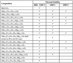
Figure IMGF000029_0001 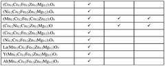
Figure IMGF000030_0001 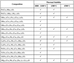
Figure IMGF000030_0002
Abstract
Description
[0001] ENHANCED EMISSIVITY IN HIGH-SPEED WINDOW MATERIALS AND RADOMES GOVERNMENT SUPPORT CLAUSE
[0001] This invention was made in part with government support under contract # N6893624C0041 awarded by the Department of the Navy. The government has certain rights in the invention. CROSS-REFERENCE TO RELATED APPLICATIONS
[0002] This application claims the benefit of U.S. Provisional Application No. 63 / 556,031, filed February 21, 2024, and entitled “High Emissivity Hypersonic Window Coatings,” the contents of which is incorporated herein by reference in its entirety. TECHNICAL FIELD
[0003] This application relates to mixed metal oxides as well as the application of said mixed metal oxides in the aerospace, power generation, and automotive fields. BACKGROUND
[0004] The development of infrared (IR) transparent windows for hypersonic flight must solve three critical problems simultaneously: transmit infrared radiation in the 3 – 5 µm range (mid- wave infrared, MWIR) and / or 8 – 12 µm range (long-wave infrared, LWIR); have high emissivity in the 0.7 to 3 µm range to dissipate heat by radiation as conduction and convection only play a minimal role under extreme flight conditions; and be chemically and mechanically stable at temperatures >1000°C in an oxidizing environment.
[0005] Oxide-based materials represent the best opportunity to withstand the highly oxidizing environments experienced by hypersonic aircraft and missiles. Disadvantageously, the spectral properties of traditional oxides are not ideal for hypersonic applications, as they typically do not emit in the spectral bands of highest Planck function energy at high temperatures (e.g., >1000°C). For example, as shown in Figure 1A, a normalized blackbody curve at 1500°C is shown as a solid line and data for a typical MWIR window (e.g., Y2O3) is shown as a dotted line. Emissivity for Y2O3(and other typical window materials such as magnesium aluminate (MgAl2O4) spinel or MgO:Y2O3nano-composite optical ceramics) is very low below 3 μm and therefore these materials will not be able to radiate effectively to stay cool during flight. Temperature reductions of 200°C or greater at a given heat flux by adding a spectrally selective high emissivity coating (dashed curve) would have a significant impact on the ability to use these materials with high confidence in stressing hypersonic environments.
[0006] Radio frequency (RF) radomes face similar constraints: transparency in the RF band of interest, broadband, high emissivity to cool the structure, and chemical and mechanical stability at >1250°C. In addition, they must have a low dielectric constant and low losses in the gigahertz (GHz) range. High-speed flight can lead to material degradation (e.g., erosion from impact with debris including sand, rain, and hale), structural instability due to the strain of high-speed flight, and compromised radar transmission due to thermal distortion of the radome.
[0007] Radomes are typically fabricated out of silicon nitride, slip cast fused silica (SCFS), and related ceramics / ceramic composites (e.g., AN-720) and are highly reflective (low-emissivity) in the spectral band where most radiative cooling occurs (1 – 5μm). Radomes would also significantly benefit from the addition of top coatings which are RF transparent, thermally stable, and highly emissive in the thermal band to remain cool during high-speed flight. Towards that end, broadband high emissivity engineered mixed metal oxides could be incorporated into a low-loss oxide binder of a material similar to the substrate and the coating impedance matched to the underlying substrate for optimal RF performance combined with high IR emissivity. Coatings may also serve as sealants for ceramic matrix composite-based radomes providing both improved performance and enhanced reliability during flight.
[0008] If window materials, radomes, and / or coatings can be engineered such that the emissivity can be raised at short wavelengths without affecting the in-band transmission of the window, then for a given heat flux the window will run much cooler. This makes material survivability at higher heat fluxes (i.e., more aggressive hypersonic missions) possible. A typical infrared window has an emissivity of ~0.1 and can reach temperatures of 1500°C in flight. Radomes face similar challenges. For example, the model in Figure 1B shows that as the spectrally averaged emissivity increases from 0.1 to 1, the window temperature falls from 1500°C to below 900°C [Saad, 2023].
[0009] Since thermal emission is a surface phenomenon, a robust coating on the order of microns in thickness on the exterior surface of a window or radome is believed to be sufficient to limit the temperature rise during high-speed operation. Thus, IR windows and RF radomes with high mechanical strength and high thermal stability developed over the last decades may still be used.
[0010] High emissivity materials are normally dark colored while low emissivity materials are generally light colored. From a naive standpoint, selective emissivity may be obtained by mixing a combination of the two types of oxides into a single material. Unfortunately, a simple addition of oxides will not solve the problem and instead a material for optimum performance during hypersonic flight needs to be engineered.
[0011] It would be an advance in the arts to provide a mixed metal oxide material comprising at least four or more metals that are more thermally stable than the physical mixtures of the constituent metal oxides. Some mixed metal oxides display spectrally selective emission and thus can be used as a coating on mid-wave infrared transparent windows (3 – 5 µm) and long-wave IR (8 – 12 µm range) transparent windows. Further, some mixed metal oxides described herein display broadband emissivity (0.5 – 15.5 µm) and high transparency in the RF (8 – 40 GHz) and thus can be used for radome applications. SUMMARY
[0012] In some aspects, mixed metal oxides that display unique advantages across the electromagnetic spectrum are described. Broadly, a mixed metal oxide comprising four or more metal species is disclosed, wherein the mixed metal oxide is (a) a spectrally selective emitter having a high emissivity in the visible / near infrared region, while being transparent in the mid- wave or long-wave infrared region; or (b) a broadband emitter having high emissivity in the visible through the infrared regions, but are transparent in the RF.
[0013] In some aspects, a mixed metal oxide comprising four or more metal species and an emissivity greater than 0.6 at a wavelength of 1 micron and an emissivity of less than 0.2 in at least one infrared wavelength is disclosed.
[0014] In some other aspects, a mixed metal oxide comprising four or more metal species and a broadband emissivity of greater than 0.7 from 0.5-15.5 μm at room temperature and greater than about 80% transmission from 8 – 40 GHz is disclosed.
[0015] In still other aspects, a solid-state process to synthesize the mixed metal oxides described herein is disclosed, said method comprising: mixing a combination or blend of metal cation precursors dry or in a liquid; optionally drying the mixture; calcining the dried mixture to produce the mixed metal oxides; and optionally grinding the mixed metal oxides and / or sieving to remove any agglomerates.
[0016] In another aspect, mixed metal oxides as described herein can be synthesized using solution based processes including, but not limited to: dissolving the metal cation precursors in solution, drying, and calcining; co-precipitation synthesis followed by drying and calcining; combustion synthesis followed by optional calcining; and sol-gel synthesis where the gel is dried and the resulting material calcined.
[0017] In other aspects, a method of coating a substrate with a material comprising a mixed metal oxide as described herein is disclosed, said method comprising physically, chemically, or both physically and chemically applying a coating comprising the material on the substrate. In some embodiments, the coating is uniformly coated. In some other embodiments, the coating is patterned.
[0018] In yet other aspects, a method of coating a substrate with a material comprising a mixed metal oxide as described herein is disclosed, wherein the method comprises: physically, chemically, or both physically and chemically applying a coating comprising a combination of metal cation precursors of the desired mixed metal oxide on the substrate; and heating either during deposition or post deposition to form a coating of the material comprising the mixed metal oxide coating on the substrate. In some embodiments, the coating is uniformly coated. In some other embodiments, the coating is patterned.
[0019] In another aspect, a substrate comprising a coating comprising any of the mixed metal oxides described herein is disclosed.
[0020] In still another aspect, a substrate comprising a pattern comprising any of the mixed metal oxides described herein is disclosed.
[0021] In yet another aspect, a substrate comprising any of the mixed metal oxides described herein incorporated directly into the substrate is disclosed.
[0022] Other aspects, features and embodiments of the invention will be more fully apparent from the ensuing disclosure and appended claims. BRIEF DESCRIPTION OF THE FIGURES
[0023] The patent or application file contains at least one drawing executed in color. Copies of this patent or patent application publication with color drawings will be provided by the Office upon request and payment of the necessary fee.
[0024] Having thus described the presently disclosed subject matter in general terms, reference will now be made to the accompanying Figures, which are not necessarily drawn to scale, and wherein:
[0025] Figure 1A. Normalized blackbody curve at 1500°C (solid), dotted: emissivity of a typical MWIR window, and dashed: ideal emission curve.
[0026] Figure 1B. Plot of the decrease in wall temperature from 1500°C as a function of spectrally averaged emissivity (based on the model in Saad, 2023).
[0027] Figure 2A. Powder XRD patterns for (Mn0.2Cr0.2Fe0.2Zn0.2Mg0.2)3O4, an infrared selective emitter, before and after heating to 1500°C.
[0028] Figure 2B. SEM images for the same dataset of Figure 2A, respectively.
[0029] Figure 3A. Powder XRD patterns for La(Fe0.2Co0.2Ni0.2Cr0.2Mn0.2)O3, a broadband infrared emitter, before and after heating to 1500°C.
[0030] Figure 3B. SEM images for this same dataset of Figure 3A, respectively.
[0031] Figure 4A. Powder X-ray diffraction pattern for an equimolar mixture of MnO2, Cr2O3, Fe2O3, ZnO, and MgO.
[0032] Figure 4B. Simulated XRD pattern for the mixture in Figure 4A.
[0033] Figure 4C. XRD pattern after calcining the material in Figure 4A to form (Mn0.2Cr0.2Fe0.2Zn0.2Mg0.2)3O4.
[0034] Figure 4D. Comparison of the infrared emission spectra for the physical mixture (top) of Figure 4A and the fully formed mixed metal oxide (bottom) of Figure 4C.
[0035] Figure 5. Infrared emission spectrum of (Mn0.2Cr0.2Fe0.2Zn0.2Mg0.2)3O4. Solid: calcined at 1100°C for 6 h, dashed: heated to 1500°C for 1h. The broad peak at ~2.8 µm is due to adsorbed water and / or surface OH groups.
[0036] Figure 6. Emissivity of selected materials at ~4 µm after calcining at 1000 - 1100°C for 5 – 6 h (solid) and after heating to 1300°C for 1h (dashed).
[0037] Figure 7A. Powder diffraction pattern of La(Mn0.2Cr0.2Fe0.2Zn0.2Mg0.2)O3showing a single-phase perovskite structure.
[0038] Figure 7B. SEM of the as-synthesized material of Figure 7A.
[0039] Figure 7C. Infrared emission spectra of La(Mn0.2Cr0.2Fe0.2Zn0.2Mg0.2)O3(top) and Y(Mn0.2Cr0.2Fe0.2Zn0.2Mg0.2)O3 (middle, dashed) with that of the spinel material, (Mn0.2Cr0.2Fe0.2Zn0.2Mg0.2)3O4.
[0040] Figure 8A. Powder X-ray diffraction patterns of (Mn0.2Cr0.2Fe0.2Zn0.2Mg0.2)3O4as synthesized.
[0041] Figure 8B. Powder X-ray diffraction patterns of (Mn0.2Cr0.2Fe0.2Zn0.2Mg0.2)3O4 after ball milling in isopropyl alcohol (IPA) for 4 h.
[0042] Figure 8C. Powder X-ray diffraction patterns of (Mn0.2Cr0.2Fe0.2Zn0.2Mg0.2)3O4 after ball milling in deionized (DI) water for 4 h.
[0043] Figure 8D. The scanning electron micrograph of the material of Figure 8A.
[0044] Figure 8E. The scanning electron micrograph of the material of Figure 8B.
[0045] Figure 8F. The scanning electron micrograph of the material of Figure 8C.
[0046] Figure 9. Infrared emission spectra of (Mn0.2Cr0.2Fe0.2Zn0.2Mg0.2)3O4 as synthesized (bottom, solid), after ball milling in deionized water for 4 h (middle, dashed), and after ball milling in isopropyl alcohol for 4 h (top, solid).
[0047] Figure 10A. Infrared emission spectrum of La(Fe0.2Ca0.2Ni0.2Cr0.2Mn0.2)O3 (top) and La(Fe0.2Co0.2Ni0.2Cr0.2Mn0.2)O3(bottom) after calcining at 1100°C for 6 h (solid) and after heating to 1300°C for 1 h (dashed).
[0048] Figure 10B. Infrared emission spectrum of (Mg0.2Co0.2Ni0.2Cu0.2Zn0.2)0.75Li0.25O (top) and (Mg0.2Co0.2Ni0.2Cu0.2Zn0.2)O (bottom) after calcining at 1100°C for 6 h (solid) and after heating to 1300°C for 1 h (dashed).
[0049] Figure 11A. Powder X-ray diffraction patterns of Pr(Fe0.2Co0.2Ni0.2Cr0.2Mn0.2)O3 (top) and La(Fe0.2Co0.2Ni0.2Cr0.2Mn0.2)O3 (bottom).
[0050] Figure 11B. Infrared emissivity of the compounds in (a) along with other Pr analogs of La compounds.
[0051] Figure 12A. RF transmission of the broadband emitters Pr(Fe0.2Co0.2Ni0.2Cr0.2Mn0.2)O3 (dot-dashed), (Mg0.2Co0.2Ni0.2Cu0.2Zn0.2)0.75Li0.25O (dotted), and La(Fe0.2Co0.2Ni0.2Cr0.2Mn0.2)O3(solid) on slip-cast fused silica (dashed) showing essentially 100% transmission from 15 to 40 GHz.
[0052] Figure 12B. RF transmission of the selective emitter (Mn0.2Cr0.2Fe0.2Zn0.2Mg0.2)3O4(solid) on a SCFS disc (dashed). The insert is a photograph of a coated SCFS disc.
[0053] Figure 13A. RF transmission of La(Fe0.2Co0.2Ni0.2Cr0.2Mn0.2)O3coated on a SCFS disc as a function of temperature from ambient to 950°C.
[0054] Figure 13B. RF transmission of Pr(Fe0.2Co0.2Ni0.2Cr0.2Mn0.2)O3 coated on a SCFS disc as a function of temperature from ambient to 950°C. The insert is a photograph of a coated SCFS disc at temperature.
[0055] Figure 14A. Time dependence of the front side surface temperature of a SCFS substrate (dashed) coated with La(Fe0.2Co0.2Ni0.2Cr0.2Mn0.2)O3(solid), (Mg0.2Co0.2Ni0.2Cu0.2Zn0.2)0.75Li0.25O (dot-dashed), and Pr(Fe0.2Co0.2Ni0.2Cr0.2Mn0.2)O3 (dotted).
[0056] Figure 14B. Time dependence of the temperature of the back side surface of a SCFS substrate (dashed) coated with La(Fe0.2Co0.2Ni0.2Cr0.2Mn0.2)O3(solid), (Mg0.2Co0.2Ni0.2Cu0.2Zn0.2)0.75Li0.25O (dot-dashed), and Pr(Fe0.2Co0.2Ni0.2Cr0.2Mn0.2)O3(dotted).
[0057] Figure 15A. Schematic drawing of a patterned film (dark gray) on an IR transparent window (light gray).
[0058] Figure 15B. The thermal profile between features is dependent on the relative thermal conductivity, emissivity, and details of the pattern.
[0059] Figure 16. An illustration of coating, patterning, and materials incorporation of the mixed metal oxides described herein onto a substrate and examples of intended uses in missile applications. DETAILED DESCRIPTION
[0060] The presently disclosed subject matter now will be described more fully hereinafter with reference to the accompanying Figures, in which some, but not all embodiments of the inventions are shown. Like numbers refer to like elements throughout. The presently disclosed subject matter may be embodied in many different forms and should not be construed as limited to the embodiments set forth herein; rather, these embodiments are provided so that this disclosure will satisfy applicable legal requirements. Therefore, it is to be understood that the presently disclosed subject matter is not to be limited to the specific embodiments disclosed and that modifications and other embodiments are intended to be included within the scope of the appended claims.
[0061] For purposes of this disclosure, the chemical elements are identified in accordance with the Periodic Table of the Elements, CAS version, Handbook of Chemistry and Physics, 75thEd., inside cover, and specific functional groups are generally defined as described therein.
[0062] "Substantially devoid" is defined herein to mean that none of the indicated substance is intentionally added or present. For example, less than about 1 wt%, preferably less than about 0.1 wt%, and even more preferably less than about 0.01 wt% of the indicated substance is present.
[0063] The term “about,” when used in connection with one or more numbers or numerical ranges, should be understood to refer to all such numbers, including all numbers in a range and modifies that range by extending the boundaries slightly above and slightly below the numerical values set forth by, for example, + / -5%. The recitation of numerical ranges by endpoints includes all numbers, e.g., whole integers, including fractions thereof, subsumed within that range (for example, the recitation of 1 to 5 includes 1, 2, 3, 4, and 5, as well as fractions thereof, e.g., 1.5, 2.25, 3.75, 4.1, and the like) and any range within that range. For the purposes of the present application, the term “about” is also intended to capture the intricate and complicated nature of crystal unit cells, wherein cation and / or anion vacancies can exist, and therefore the number of atoms, e.g., oxygen, in a unit cell is more or less than the expected integer value. For example, in an idealized compound, the number of oxygen atoms in the chemical formula is 1, but in an as- synthesized compound, the number of oxygen atoms in the chemical formula may be in a range from 0.95 to 1.05 (i.e., + / -), as understood by the skilled artisan in the art.
[0064] As defined herein, “substantially similar” when used in connection with one or more numbers or numerical ranges, should be understood to refer to all such numbers, including all numbers in a range and modifies that range by extending the boundaries slightly above and slightly below the numerical values set forth by, for example, + / -5%. To capture the intricate and complicated nature of crystal unit cells, there is disclosure herein of non-integer numbers being substantially similar (e.g., y1, y2, y3, y4, and y5 are about the same values), since in an as- synthesized compound, these values can be substantially similar but may not be exactly equal, as understood by the skilled artisan in the art.
[0065] The phrase “in one embodiment” or “in some embodiments” as used herein does not necessarily refer to the same embodiment, though it may. Furthermore, the phrase “in another embodiment” as used herein does not necessarily refer to a different embodiment, although it may. Thus, as described below, various embodiments of the invention may be readily combined, without departing from the scope or spirit of the invention.
[0066] The terms “comprise(s),” “include(s),” “having,” “has,” “can,” “contain(s),” and variants thereof, as used herein, are intended to be open-ended transitional phrases, terms, or words that do not preclude the possibility of additional acts or structures. The singular forms “a,” “and” and “the” include plural references, i.e., “one or more,” unless the context clearly dictates otherwise. The present disclosure also contemplates other embodiments “comprising,” “consisting of” and “consisting essentially of,” the embodiments or elements presented herein, whether explicitly set forth or not. Likewise, the term “include” and its grammatical variants are intended to be non- limiting, such that recitation of items in a list is not to the exclusion of other like items that can be substituted or added to the listed items.
[0067] As defined herein, a “photomask” or “shadow mask” refers to a pre-patterned stencil that allows either light or electrons to pass through onto deposited resist where the defined pattern is.
[0068] As used herein, “mixed metal oxides” or “multicomponent mixed metal oxides” are materials that can modulate the IR emissivity of materials by exercising compositional and defect (e.g., oxygen and / or cation vacancies) control. In some embodiments, the melting point of a mixed metal oxide is greater than that of the constituent oxides [Wang, 2022].
[0069] It should be appreciated by the person skilled in the art that any numerical values shown as ranges hereinafter, e.g., 0.20-0.30, include any values to the hundredths place between the higher and lower values provided, i.e., 0.20, 0.21, 0.22, 0.23, 0.24, 0.25, 0.26, 0.27, 0.28, 0.29 and 0.30. Mixed metal oxides
[0070] Broadly, the presently disclosed subject matter relates to mixed metal oxide materials having superior spectrally selective emissivity or broadband emissivity, wherein some materials display minimal changes in structure (XRD), particle size (SEM), and infrared emissivity after heating to 1500°C for 1 h, making them excellent options as coatings on MWIR windows, LWIR windows, or radomes. Advantageously, the spectrally selective emitters have high emissivity in the visible / near infrared regions and are transparent in the mid-wave or long-wave IR regions, while the broadband emitters have high emissivity in the visible region and through the infrared region, but are transparent in the RF. Many materials are durable, oxidatively stable, have high- emissivity, and are inexpensive to produce. The synthesis and optimization of highly engineered coatings comprising mixed metal oxides ensures their application in markets such as defense, energy, medical, and transportation.
[0071] In a first aspect, a spectrally selective emissivity material is described, wherein the spectrally selective emissivity material is a mixed metal compound comprising at least three of Mg, Ca, Cr, Mn, Fe, Co, Ni, Cu, Zn, La, Y, Al, Pr, Sr, Ba, Ti, V, Zr, Nb, Mo, Tc, Cd, Hf, Ta, W, Sc, Ce, Nd, Pm, Sm, Eu, Gd, Tb, Dy, Ho, Er, Tm, Yb, Lu, Re, Pt, Pd, Ir, Au, Ag, Ru, Rh, and / or Os. In some embodiments, the mixed metal compound is an oxide, an oxysulfide, an oxychloride, or any combination thereof. In some embodiments, the mixed metal compound is an oxide. In some embodiments, the spectrally selective emissivity material is a mixed metal oxide comprising at least four of Mg, Ca, Cr, Mn, Fe, Co, Ni, Cu, Zn, La, Y, Al, Pr, Sr, Ba, Ti, V, Zr, Nb, Mo, Tc, Cd, Hf, Ta, W, Sc, Ce, Nd, Pm, Sm, Eu, Gd, Tb, Dy, Ho, Er, Tm, Yb, Lu, Re, Pt, Pd, Ir, Au, Ag, Ru, Rh, and / or Os. In some embodiments, the spectrally selective emissivity material is a mixed metal oxide comprising at least four metals selected from Mg, Ca, Cr, Mn, Fe, Co, Ni, Cu, Zn, La, Y, Al, and / or Pr. In some embodiments, the spectrally selective emissivity material is a mixed metal oxide comprising at least five metals selected from Mg, Ca, Cr, Mn, Fe, Co, Ni, Cu, Zn, La, Y, Al, and / or Pr. In some embodiments, the spectrally selective emissivity material is a mixed metal oxide comprising five metals selected from Mg, Ca, Cr, Mn, Fe, Co, Ni, Cu, Zn. For ease of reference hereinafter, the spectrally selective emissivity mixed metal oxides will hereinafter be referred to as SSE mixed metal oxides. In some embodiments, any of the SSE mixed metal oxides can be doped, for example with alkali metals or alkaline earth metals such as Li, Mg, Si, and / or Ca. In some embodiments, the SSE mixed metal oxide has an emissivity greater than 0.6 at a wavelength of 1 micron (i.e., a “high emissivity in visible and near infrared”) and an emissivity of less than 0.2 in at least one infrared wavelength (i.e., a “low emissivity in IR”). In some embodiments, the SSE mixed metal oxide has a spinel structure. In some embodiments, the SSE mixed metal oxide has a perovskite structure. In some embodiments, the SSE mixed metal oxide has a perovskite structure and comprises five metals selected from Mg, Ca, Cr, Mn, Fe, Co, Ni, Cu, Zn and one metal selected from La, Y, Al, and / or Pr. In some embodiments, the SSE mixed metal oxide has a fluorite structure. In some embodiments, the SSE mixed metal oxide has a cubic structure. In some embodiments, the SSE mixed metal oxide transmits radiation in the 3 – 5 µm range.
[0072] While no transparency in the MWIR range is required, in some embodiments, the mixed metal oxides have high emissivity, a high melting point, stability in a high temperature oxidizing environment for long periods of time, low thermal conductivity, a thermal expansion coefficient matching that of the underlaying alloy and ideally are self-healing if defects form. These mixed metal oxides are considered broad spectrum emitters.
[0073] In some embodiments, the hardness of a SSE mixed metal oxide containing 5 metal ions can be far greater than that of the constituent oxides or even that of the materials formed from 2, 3, or 4 metal ions. Thus, without being bound by theory, it is believed that the durability of the underlying window may be improved when covered with a thin film of SSE mixed metal oxide.
[0074] In some embodiments of the first aspect, the SSE mixed metal oxides have the general formula selected from: (a) ((M1)w1(M2)w2(M3)w3)3O4, (b) ((M1)x1(M2)x2(M3)x3(M4)x4)3O4, (c) ((M1)y1(M2)y2(M3)y3(M4)y4(M5)y5)3O4, or (d) M6((M1)z1(M2)z2(M3)z3(M4)z4(M5)z5)O3, wherein M1, M2, M3, M4, M5, and M6 represent different metal species, M6 has anionic charge of about +3, the sum of (w1+w2+w3) is about 1, the sum of (x1+x2+x3+x4) is about 1, the sum of (y1+y2+y3+y4+y5) is about 1, and the sum of (z1+z2+z3+z4+z5) is about 1 and the stoichiometry of the oxygen anions varies from the ideal to compensate for the stoichiometry of the metal cations.
[0075] In some embodiments of the first aspect, the SSE mixed metal oxide has the formula ((M1)w1(M2)w2(M3)w3)3O4, wherein the sum of (w1+w2+w3) is about 1. In some embodiments, M1, M2, and M3 are independently selected from Mg, Ca, Cr, Mn, Fe, Co, Ni, Cu, and / or Zn. In some embodiments, M1, M2 and M3 are Mn, Zn and Mg. In some embodiments, w1 is in a range from 0.20-0.40, w2 is in a range from 0.20-0.40, and w3 is in a range from 0.20-0.40. In some other embodiments, w1 is in a range from 0.30-0.40, w2 is in a range from 0.30-0.40, and w3 is in a range from 0.30-0.40. In some embodiments, w1, w2 and w3 have substantially similar values. In some embodiments, w1, w2 and w3 are 0.33. In some other embodiments, at least one of w1, w2, and w3 has a different value than the others. In some embodiments, the SSE mixed metal oxide has the formula ((Mn)0.33(Zn)0.33(Mg)0.33)3O4.
[0076] In some embodiments of the first aspect, the SSE mixed metal oxide has the formula ((M1)x1(M2)x2(M3)x3(M4)x4)3O4, wherein the sum of (x1+x2+x3+x4) is about 1. In some embodiments, M1, M2, M3, and M4 are independently selected from Mg, Ca, Cr, Mn, Fe, Co, Ni, Cu, and / or Zn. In some embodiments, M1, M2, M3, and M4 are selected from Mn, Cr, Fe, Zn, and Mg. In some embodiments, M1, M2, M3, and M4 are: Mn, Cr, Zn, and Mg; or Mn, Fe, Zn, and Mg; or Mn, Cr, Fe, and Zn; or Mn, Cr, Fe, and Mg. In some embodiments, x1 is in a range from 0.20-0.30, x2 is in a range from 0.20-0.30, x3 is in a range from 0.20-0.30, and x4 is in a range from 0.20-0.30. In some other embodiments, x1 is in a range from 0.23-0.27, x2 is in a range from 0.23-0.27, x3 is in a range from 0.23-0.27, and x4 is in a range from 0.23-0.27. In some embodiments, x1, x2, x3, and x4 have substantially similar values. In some embodiments, x1, x2, x3, and x4 are 0.25. In some other embodiments, at least one of x1, x2, x3, and x4 has a different value than the others. In some embodiments, the SSE mixed metal oxide has the formula: ((Mn)0.25(Cr)0.25(Zn)0.25(Mg)0.25)3O4; or ((Mn)0.25(Fe)0.25(Zn)0.25(Mg)0.25)3O4; or ((Mn)0.25(Cr)0.25(Fe)0.25(Zn)0.25)3O4; or ((Mn)0.25(Cr)0.25(Fe)0.25(Mg)0.25)3O4.
[0077] In some embodiments of the first aspect, the SSE mixed metal oxide has the formula ((M1)y1(M2)y2(M3)y3(M4)y4(M5)y5)3O4, wherein the sum of (y1+y2+y3+y4+y5) is about 1. In some embodiments, M1, M2, M3, M4, and M5 are selected from Mg, Ca, Cr, Mn, Fe, Co, Ni, Cu, and / or Zn. In some embodiments, one of M1, M2, M3, M4, or M5 is Mg. In some embodiments, M1, M2, M3, M4, and M5 are: Mn, Cr, Fe, Zn, and Mg; or Mn, Fe, Zn, Mg, and Ca; or Mn, Fe, Zn, Mg, and Co; or Cr, Fe, Zn, Mg, and Co; or Cr, Fe, Zn, Mg, and Ni. In some embodiments, y1 is in a range from 0.05-0.35, y2 is in a range from 0.05-0.35, y3 is in a range from 0.05-0.35, y4 is in a range from 0.05-0.35, and y5 is in a range from 0.05-0.35. In some other embodiments y1≅y2≅y3 and are in a range from 0.15 to 0.25, y4 is in a range from 0.05-0.35, and y5 is in a range from 0.05-0.35. In some embodiments, y1, y2, y3, y4, and y5 have substantially similar values. In some embodiments, y1, y2, y3, y4, and y5 are 0.20. In some other embodiments, at least one of y1, y2, y3, y4, and y5 has a different value than the others. In some embodiments, the SSE mixed metal oxide has the formula (Mn0.15-0.25Cr0.15-0.25Fe0.15-0.25Zn0.05-0.35Mg0.05-0.35)3O4. In some embodiments, the SSE mixed metal oxide has the formula: (Mn0.2Cr0.2Fe0.2Zn0.2Mg0.2)3O4; or (Mn0.2Ca0.2Fe0.2Zn0.2Mg0.2)3O4; or (Mn0.2Cr0.2Fe0.2Mg0.15Zn0.25)3O4; or (Mn0.2Cr0.2Fe0.2Mg0.25Zn0.15)3O4; or (Mn0.18Cr0.18Fe0.18Zn0.23Mg0.23)3O4; or (Mn0.2Cr0.2Fe0.2Zn0.1Mg0.3)3O4; or (Mn0.2Cr0.2Fe0.2Zn0.3Mg0.1)3O4; or (Mn0.2Co0.2Fe0.2Zn0.2Mg0.2)3O4; or (Co0.2Cr0.2Fe0.2Zn0.2Mg0.2)3O4; or (Ni0.2Cr0.2Fe0.2Zn0.2Mg0.2)3O4.
[0078] In some embodiments of the first aspect, the SSE mixed metal oxide and has the formula M6((M1)z1(M2)z2(M3)z3(M4)z4(M5)z5)O3, wherein the sum of (z1+z2+z3+z4+z5) is about 1. In some embodiments, M1, M2, M3, M4, and M5 are selected from Mg, Ca, Cr, Mn, Fe, Co, Ni, Cu, and / or Zn, and M6 is selected from La, Y, Pr or Al. In some embodiments, M1, M2, M3, M4, and M5 are selected from Mn, Cr, Fe, Zn, Mg, Ca, Co, and / or Ni, and M6 is selected from La, Y or Al. In some embodiments, M1, M2, M3, M4, and M5 are: Mn, Cr, Fe, Zn, and Mg; or Mn, Fe, Zn, Mg, and Ca; or Mn, Fe, Zn, Mg, and Co; or Cr, Fe, Zn, Mg, and Co; or Cr, Fe, Zn, Mg, and Ni. In some embodiments, M6 is La. In some embodiments, M6 is Y. In some embodiments, M6 is Al. In some embodiments, M6 is Pr. In some embodiments, z1 is in a range from 0.05-0.35, z2 is in a range from 0.05-0.35, z3 is in a range from 0.05-0.35, z4 is in a range from 0.05-0.35, and z5 is in a range from 0.05-0.35. In some other embodiments z1≅z2≅z3 and are in a range from 0.15 to 0.25, z4 is in a range from 0.05-0.35, and z5 is in a range from 0.05-0.35. In some embodiments, z1, z2, z3, z4, and z5 have substantially similar values. In some embodiments, z1, z2, z3, z4, and z5 are 0.20. In some other embodiments, at least one of z1, z2, z3, z4, and z5 has a different value than the others. In some embodiments, the SSE mixed metal oxide has the formula M6(Mn0.15-0.25Cr0.15-0.25Fe0.15-0.25Zn0.05-0.35Mg0.05-0.35)O3. In some embodiments, the SSE mixed metal oxide has the formula: La(Mn0.2Cr0.2Fe0.2Zn0.2Mg0.2)O3; or Y(Mn0.2Cr0.2Fe0.2Zn0.2Mg0.2)O3; or Al(Mn0.2Cr0.2Fe0.2Zn0.2Mg0.2)O3. In some embodiments, the SSE mixed metal oxide having the general formula M6((M1)z1(M2)z2(M3)z3(M4)z4(M5)z5)O3 is a perovskite or a multi-phase material.
[0079] “Light” colored metal oxides such as Li2O, Mg, Al2O3, CaO, TiO2, V2O5, ZnO, SrO, Y2O3, ZrO2, MoO3, SnO2, La2O3, CeO2, Sm2O3, Eu2O3, HfO2, Ta2O5, and WO3are typically more transparent in the infrared region than “dark” colored metal oxides such as CrO, Cr2O3, MnO2, Mn2O3, Mn3O4, FeO, Fe2O3, Fe3O4, CoO, NiO, CuO, Cu2O, Pr6O11, and ReO2. From a simplistic standpoint, one might choose a mixture of “light” and “dark” oxides to form an infrared selective emitting material – the more “light,” the more transparent and the more “dark,” the more emissive. This simplistic view of materials development is incorrect though and unexpectedly, adding a “light” oxide to a mixed metal oxide can increase the emissivity while adding a “dark” oxide can decrease the emissivity. This evidences that there is an unexpected electronic interaction between the metal cations and that it is not trivial to engineer a superior material.
[0080] A summary of the advantages of the SSE mixed metal oxides of the first aspect and coatings thereof with spectrally selective emissivity described herein include: • Both “dark” and “light” metal oxides are required for a successful selective emitter, but the results are not additive, thus requiring engineering of the mixed metal oxide. o Spinel structures can tolerate significant changes in metal stoichiometry (e.g., removal of Cr, Fe, Mg, Zn) or replacement of Cr or Fe with Ca, Ni, Co). o Spinel structures can be converted to a perovskite structure with the addition of an “A” metal cation (e.g., La, Y). • The mixed metal oxide with 4 or more different metals perform better than those with less than 4 different metal atoms. • Particle sizes may be controlled by milling and / or alternative synthetic procedures. The mixed metal oxides are stable to at least 1300°C in air. • Minimal changes in structure (XRD), particle size (SEM), and infrared emissivity after heating in air to 1500°C for 1 h confirm the outstanding stability of some of the mixed metal oxides described herein. • Emissivity greater than 0.6 at 1 µm, 0.55 at 1.5 µm, and less than 0.015 at 4 µm at room temperature has been measured. • Small variations in the stoichiometry have a minimal effect on the optimized emission spectrum. o Yield remains near 100% o The process window is large making mixed metal oxide scale-up simpler and less costly. • The spectrally selective emissivity materials are water insoluble. • Based on the emissivity profile, a front side window cooling of at least 200°C (e.g., from 1500°C to 1300°C) is expected. • Coatings are robust to at least 1000°C showing no cracking or scaling after heating. • Ideal for selective infrared emitter coatings for MWIR and LWIR windows
[0081] In a second aspect, a broadband emissivity material is described, wherein the broadband emissivity material is a mixed metal compound comprising at least three of Mg, Ca, Cr, Mn, Fe, Co, Ni, Cu, Zn, La, Y, Al, Pr, Sr, Ba, Ti, V, Zr, Nb, Mo, Tc, Cd, Hf, Ta, W, Sc, Ce, Nd, Pm, Sm, Eu, Gd, Tb, Dy, Ho, Er, Tm, Yb, Lu, Re, Pt, Pd, Ir, Au, Ag, Ru, Rh, and / or Os. In some embodiments, the mixed metal compound is an oxide, an oxysulfide, an oxychloride, or any combination thereof. In some embodiments, the mixed metal compound is an oxide. In some embodiments, the broadband emissivity material is a mixed metal oxide comprising at least four of Mg, Ca, Cr, Mn, Fe, Co, Ni, Cu, Zn, La, Y, Al, Pr, Sr, Ba, Ti, V, Zr, Nb, Mo, Tc, Cd, Hf, Ta, W, Sc, Ce, Nd, Pm, Sm, Eu, Gd, Tb, Dy, Ho, Er, Tm, Yb, Lu, Re, Pt, Pd, Ir, Au, Ag, Ru, Rh, and / or Os. In some embodiments, the broadband emissivity material is a mixed metal oxide comprising at least three of Ca, Cr, Mn, Fe, Co, Ni, Cu, Zn, La, Y, Al, and / or Pr. In some embodiments, the broadband emissivity material is a mixed metal oxide comprising at least four of Ca, Cr, Mn, Fe, Co, Ni, Cu, Zn, La, Y, Al, and / or Pr. In some embodiments, the broadband emissivity material is a mixed metal oxide comprising at least five of Ca, Cr, Mn, Fe, Co, Ni, Cu, Zn, La, Y, Al, and / or Pr. In some embodiments, the broadband emissivity material is a mixed metal oxide comprising at least six of Ca, Cr, Mn, Fe, Co, Ni, Cu, Zn, La, Y, Al, and / or Pr. For ease of reference hereinafter, the broadband emissivity mixed metal oxides will hereinafter be referred to as BB mixed metal oxides. In some embodiments, any of the BB mixed metal oxides can be doped, for example with alkali metals or alkaline earth metals such as Li, Mg, Si, and / or Ca. In some embodiments, the BB mixed metal oxide has a spinel structure. In some embodiments, the BB mixed metal oxide has a perovskite structure. In some embodiments, the BB mixed metal oxide has a fluorite structure. In some embodiments, the BB mixed metal oxide has a cubic structure.
[0082] In some embodiments of the second aspect, the BB mixed metal oxides have the general formula selected from: (a) ((M1)a1(M2)a2(M3)a3(M4)a4)3O4, (b) ((M1)b1(M2)b2(M3)b3(M4)b4(M5)b5)3O4, (c) M6((M1)c1(M2)c2)O3, (d) M6((M1)d1(M2)d2(M3)d3)O3, or (e) M6((M1)e1(M2)e2(M3)e3(M4)e4(M5)e5)O3, wherein M1, M2, M3, M4, M5, and M6 represent different metal species, M6 has anionic charge of about +3 ionic charge, the sum of (a1+a2+a3+a4) is about 1, the sum of (b1+b2+b3+b4+b5) is about 1, the sum of (c1+c2) is about 1, the sum of (d1+d2+d3) is about 1, and the sum of (e1+e2+e3+e4+e5) is about 1.
[0083] In some embodiments of the second aspect, the BB mixed metal oxide has the formula ((M1)a1(M2)a2(M3)a3(M4)a4)3O4, wherein the sum of (a1+a2+a3+a4) is about 1. In some embodiments, M1, M2, M3, and M4 are independently selected from Ca, Cr, Mn, Fe, Co, Ni, Cu, and / or Zn. In some embodiments, M1, M2, M3, and M4 are independently selected from Ca, Cr, Mn, Fe, Co, Ni, Cu, and / or Zn. In some embodiments, M1, M2, M3, and M4 are selected from Mn, Cr, Fe, Ca, Co, and Cu. In some embodiments, M1, M2, M3, and M4 are Mn, Cr, Fe, and Cu. In some embodiments, a1 is in a range from 0.20-0.30, a2 is in a range from 0.20-0.30, a3 is in a range from 0.20-0.30, and a4 is in a range from 0.20-0.30. In some other embodiments, a1 is in a range from 0.23-0.27, a2 is in a range from 0.23-0.27, a3 is in a range from 0.23-0.27, and a4 is in a range from 0.23-0.27. In some embodiments, a1, a2, a3, and a4 have substantially similar values. In some embodiments, a1, a2, a3, and a4 are 0.25.In some other embodiments, at least one of a1, a2, a3, and a4 has a different value than the others. In some embodiments, the BB mixed metal oxide has the formula ((Mn)0.25(Cr)0.25(Fe)0.25(Cu)0.25)3O4.
[0084] In some embodiments of the second aspect, the BB mixed metal oxide has the formula ((M1)b1(M2)b2(M3)b3(M4)b4(M5)b5)3O4, wherein the sum of (b1+b2+b3+b4+b5) is about 1. In some embodiments, M1, M2, M3, M4, and M5 are selected from Mn, Cr, Fe, Zn, Ca, Co, Cu, and / or Ni. In some embodiments, one of M1, M2, M3, M4, or M5 is Cu. In some embodiments, M1, M2, M3, M4, and M5 are: Mn, Fe, Cu, Ca, and Co; or Mn, Cr, Fe, Cu, and Ca. In some embodiments, b1 is in a range from 0.05-0.35, b2 is in a range from 0.05-0.35, b3 is in a range from 0.05-0.35, b4 is in a range from 0.05-0.35, and b5 is in a range from 0.05-0.35. In some other embodiments b1≅b2≅b3 and are in a range from 0.15 to 0.25, b4 is in a range from 0.05-0.35, and b5 is in a range from 0.05-0.35. In some embodiments, b1, b2, b3, b4, and b5 have substantially similar values. In some embodiments, b1, b2, b3, b4, and b5 are 0.20. In some other embodiments, at least one of b1, b2, b3, b4, and b5 has a different value than the others. In some embodiments, the BB mixed metal oxide has the formula: (Mn0.2Ca0.2Fe0.2Co0.2Cu0.2)3O4; or (Mn0.2Cr0.2Fe0.2Ca0.2Cu0.2)3O4.
[0085] In some embodiments of the second aspect, the BB mixed metal oxide and has the formula M6((M1)c1(M2)c2)O3, wherein the sum of (c1+c2) is about 1. In some embodiments, M1 and M2 are selected from Ca, Cr, Mn, Fe, Co, Ni, Cu, and / or Zn, and M6 is selected from Pr, La, Y or Al. In some embodiments, M1 and M2 are: Mn and Cr. In some embodiments, M6 is Pr, La or Y. In some embodiments, c1 is in a range from 0.30-0.70 and c2 is in a range from 0.30-0.70. In some embodiments, c1 is in a range from 0.40-0.60 and c2 is in a range from 0.40-0.60. In some embodiments, c1 and c2 have substantially similar values. In some embodiments, c1 and c2 are 0.20. In some other embodiments, c1 and c2 are different. In some embodiments, the BB mixed metal oxide has the formula Pr(Cr0.5Mn0.5)O3. In some embodiments, the BB mixed metal oxide having the general formula M6((M1)c1(M2)c2)O3 is a perovskite or a multi-phase material.
[0086] In some embodiments of the second aspect, the BB mixed metal oxide and has the formula M6((M1)d1(M2)d2(M3)d3)O3, wherein the sum of (d1+d2+d3) is about 1. In some embodiments, M1, M2, and M3 are selected from Ca, Cr, Mn, Fe, Co, Ni, Cu, and / or Zn, and M6 is selected from Pr, La, Y or Al. In some embodiments, M1, M2, and M3 are Mn, Cr, and Ni. In some embodiments, d1 is in a range from 0.20-0.40, d2 is in a range from 0.20-0.40, and d3 is in a range from 0.20-0.40. In some other embodiments, d1 is in a range from 0.30-0.40, d2 is in a range from 0.30-0.40, and d3 is in a range from 0.30-0.40. In some embodiments, d1, d2 and d3 have substantially similar values. In some embodiments, d1, d2 and d3 are 0.33. In some other embodiments, at least one of d1, d2 and d3 has a different value than the others. In some embodiments, the BB mixed metal oxide has the formula Pr(Cr0.33Mn0.33Ni0.33)O3. In some embodiments, the BB mixed metal oxide having the general formula M6((M1)d1(M2)d2(M3)d3)O3 is a perovskite or a multi-phase material.
[0087] In some embodiments of the second aspect, the BB mixed metal oxide and has the formula M6((M1)e1(M2)e2(M3)e3(M4)e4(M5)e5)O3, wherein the sum of (e1+e2+e3+e4+e5) is about 1. In some embodiments, M1, M2, M3, M4, and M5 are selected from Ca, Cr, Mn, Fe, Co, Ni, Cu, and / or Zn, and M6 is selected from Pr, La, Y or Al. In some embodiments, M1, M2, M3, M4, and M5 are: Mn, Cr, Fe, Co, and Ni; or Mn, Cr, Fe, Ca, and Ni. In some embodiments, M6 is La. In some embodiments, M6 is Y. In some embodiments, M6 is Al. In some embodiments, M6 is Pr. In some embodiments, e1 is in a range from 0.05-0.35, e2 is in a range from 0.05-0.35, e3 is in a range from 0.05-0.35, e4 is in a range from 0.05-0.35, and e5 is in a range from 0.05-0.35. In some other embodiments e1≅e2≅e3 and are in a range from 0.15 to 0.25, e4 is in a range from 0.05-0.35, and e5 is in a range from 0.05-0.35. In some embodiments, e1, e2, e3, e4, and e5 have substantially similar values. In some embodiments, e1, e2, e3, e4, and e5 are 0.20. In some other embodiments, at least one of e1, e2, e3, e4, and e5 has a different value than the others. In some embodiments, the BB mixed metal oxide has the formula: Pr(Fe0.2Co0.2Ni0.2Cr0.2Mn0.2)O3; or La(Fe0.2Ca0.2Ni0.2Cr0.2Mn0.2)O3; or Y(Fe0.2Co0.2Ni0.2Cr0.2Mn0.2)O3; or Al(Fe0.2Co0.2Ni0.2Cr0.2Mn0.2)O3. In some embodiments, the BB mixed metal oxide having the general formula M6((M1)e1(M2)e2(M3)e3(M4)e4(M5)e5)O3 is a perovskite or a multi-phase material.
[0088] In some embodiments of the second aspect, the BB mixed metal oxides are doped and have a cubic structure. Illustrative compounds include, but are not limited to: (Mg0.2Co0.2Ni0.2Cu0.2Zn0.2)iLijO or (Mg0.1Ca0.1Co0.2Ni0.2Cu0.2Zn0.2)iLijO, wherein i+j is about 1, such as (Mg0.1Ca0.1Co0.2Ni0.2Cu0.2Zn0.2)0.75Li0.25O; (Mg0.2Co0.2Ni0.2Cu0.2Zn0.2)kLilAlmO, wherein k+l+m is about 1, such as (Mg0.2Co0.2Ni0.2Cu0.2Zn0.2)0.9Li0.05Al0.05O; and (Mg0.2Ni0.2Co0.2Fe0.2Zn0.2)p(SiqAlr)O2, wherein p+q+r is about 2, such as (Mg0.2Ni0.2Co0.2Fe0.2Zn0.2)(Si0.5Al0.5)O2.
[0089] A summary of the advantages of the BB mixed metal oxides and coatings with broadband emissivity described herein includes: • Broadband high emissivity materials may be fabricated using an industrially scaled solid- state process with essentially 100% yield. Perovskite, spinel, and cubic materials can all be effective. • Materials demonstrate an emissivity ~0.9 from 0.5-15.5 µm at room temperature and greater than about 80% transmission from 8 – 40 GHz. Approximately 100% transmission from 8 – 40 GHz is maintained to at least 1000°C. • Adsorbed OH groups and / or water vapor which may limit the transmission in the MWIR window is not an issue. • Thermal stability to at least 1500°C in air for 1 h as measured by powder X-ray diffraction, scanning electron microscopy, and infrared emissivity. • Materials maintain high emissivity at relevant operating temperatures. • A demonstrated greater than 400°C temperature decrease from ~1400°C to <1000°C is demonstrated for the front side of the window and a decrease from ~850°C to ~650°C for the backside of the window. • Coatings are robust to at least 1000°C showing no cracking or scaling after heating. • Ideal for RF transparent coatings for radomes requiring visible through far infrared emissivity while maintaining near 100% transparency in at least one of the key RF bands.
[0090] In some embodiments, the mixed metal oxides of the first or second aspect (a) are substantially devoid of any precious metals selected from Au, Ag, Ru, Rh, Os, Ir, Pt, Pd, and Re, (b) are substantially devoid of Zr, (c) are substantially devoid of Hf, (d) are substantially devoid of Si, (e) are substantially devoid of Ti, (f) comprise Mn when they have a perovskite structure, (g) do not include (Fe0.2Co0.2Ni0.2Cu0.2Zn0.2)O / Fe2O4, (h) do not include (Fe0.2Co0.2Ni0.2Cu0.2Zn0.2)O / Fe2O4(MgNiCoCuZn)O, (i) all of (a)-(h), or (j) any combination of (a)-(h). Method of making the mixed metal oxides
[0091] In some embodiments, the mixed metal oxides of the first or second aspect are produced using well-known methods in the arts. For example, the mixed metal oxides of the first or second aspect can be synthesized using an industrially scalable solid-state processes. Accordingly, in a third aspect, a solid-state process to synthesize the mixed metal oxides of the first or second aspect is described, said method comprising: mixing a combination or blend of metal cation precursors, dry or in a liquid; optionally drying the mixture; calcining the dried mixture to produce the mixed metal oxides; and optionally grinding the mixed metal oxides and / or sieving to remove any agglomerates.
[0092] In some embodiments, the metal cation precursors are chosen based on the desired mixed metal oxide and the correct stoichiometry of the elements. In some embodiments, the metal cation precursors used comprise just one metal species (e.g., MnO2). In other embodiments, the metal cation precursors used comprise more than one metal species, e.g., Cr2MnO4). In some embodiments, all the metal cation precursors used as reactants are single metal species. In some other embodiments, mixtures of single metal species and metal cation precursors comprising more than one metal species are used as reactants. In some other embodiments, only metal cation precursors comprising more than one metal species are used as reactants. In some embodiments, the anions in the metal cation precursors are selected from oxides, nitrates, carbonates, acetates, nitrites, sulfates, sulfites, chlorates, chlorites, hydroxides, phosphates, etc. In some embodiments, the anions in the metal cation precursors are oxides. It should be appreciated by the person skilled in the art the anions in all of the metal cation precursors used do not have to be the same.
[0093] In some embodiments, dry metal cation precursors are mixed. In some other embodiments, the metal cation precursors are mixed in a liquid, e.g., water or an aqueous solution. In some embodiments, the mixing is effectuated for time in a range from about 30 min to about 16 hours, or about 2 hr to about 4 hr. In some embodiments, the mixing can be effectuated in a planetary ball mill or a jar roller mill, e.g., with yttria-stabilized zirconia jars and balls, however the person skilled in the art can readily identify a mixing process that efficiently blends the metal cation precursors. In some embodiments, the mixture is dried at about 60 – 150°C, or about 80 – 120°C. In some embodiments, the blended mixture is dried at the chosen temperature for time in a range from about 6 hours to about 12 hours, e.g., overnight. In some embodiments, the calcining is effectuated at temperature greater than about 900°C, e.g., in a range from about 1000 – 1200°C. In some embodiments, the calcining is effectuated in a rotary furnace to ensure the correct heat transfer during the calcining process. In some embodiments, the calcining at the chosen temperature is effectuated in air. In some embodiments, the calcining at the chosen temperature occurs for time in a range from about 4 to about 8 hours, or about 5 to about 6 hours. In some embodiments, the heating rate of calcination is about 5°C / min. In some embodiments, high-purity, single-phase mixed metal oxides are synthesized in a single-step, solid-state process with ~100% yield.
[0094] In some embodiments, using the method of synthesis of the third aspect, the SSE mixed metal oxides are single-phase. In some embodiments, using the method of synthesis of the third aspect, the BB mixed metal oxides are single-phase.
[0095] Experimentally, many of the primary particle sizes of the post-calcined mixed metal oxides are in the micron range, although agglomerates can be larger, making them subject to Mie scattering. Accordingly, in some embodiments, the average particle size of the as-synthesized mixed metal oxides is reduced, to reduce scattering, by grinding the mixed metal oxides in a planetary ball mill, e.g., with yttria-stabilized zirconia jars and balls. In some embodiments, the grinding is effectuated in the presence of water, an alcohol, such as ethanol or isopropyl alcohol, or an aqueous solution comprising an alcohol. In some embodiments, the ground mixed metal oxides are further sieved to remove any remaining clumps. In some embodiments, the ground mixed metal oxides retain their single-phase structure and no new impurity phases are introduced by the process of grinding (see, for example, Figures 8A-8C). In some embodiments, the mixed metal oxides are not ground but are sieved to obtain a favored size. In some embodiments, for example, spray drying may be used where particle sizes in a range from about 1 to about 60 μm are required for subsequent coating processes.
[0096] In a fourth aspect, a solution-based process to synthesize a mixed metal oxide of the first or second aspect is described, said method comprising dissolving the appropriate metal cation precursors, as described herein for the third aspect, in an appropriate solvent ; removing the solvent; calcining the mixture to produce the mixed metal oxides; and optionally grinding the mixed metal oxides and / or and sieving to remove any agglomerates. In some embodiments, the solvents are selected from water, alcohols, and hydrocarbons.
[0097] In a fifth aspect, a solution-based process to synthesize a mixed metal oxide of the first or second aspect is described. In some embodiments, the method comprises dissolving appropriate metal cation precursors as described herein in a solvent; adding a reagent to increase the pH (e.g., ammonia, ammonium carbonate, a hydroxide salt); filtering and washing the precipitate formed; calcining the mixture to produce the mixed metal oxides; and optionally grinding the mixed metal oxides and / or and sieving to remove any agglomerates. In some other embodiments, the method comprises dissolving appropriate metal cation precursors as described herein in a solvent; adding a fuel (e.g., urea, carbohydrazide, oxalydihydrazide, glycine, citric acid, polyacrylic acid, hydrazine, etc.); heating the solution to a temperature above about 300oC until the solid reaction product forms; and, if required, calcining and then optionally grinding the mixed metal oxide powder and / or and sieving to remove any agglomerates. . In some other embodiments, the method comprises dissolving appropriate metal cation precursors as described herein in a solvent; adding a chelating agent (e.g., citric acid, ethylenediaminetetraacetic acid EDTA, etc.); heating up the solution under stirring until a gel forms; and calcining the gel into a mixed metal oxide powder; and optionally grinding the mixed metal oxide powder and / or and sieving to remove any agglomerates. In some embodiments, the solvents are selected from water, alcohols, and hydrocarbons.
[0098] It should be appreciated by the person skilled in the art that the oxygen stoichiometry can be selected to control the optical properties and the electrical and ionic conductivity of the mixed metal oxides and any coating comprising same. Coatings comprising the mixed metal oxides disclosed herein
[0099] These mixed metal oxide of the first aspect described herein with optimized spectral selectivity may be implemented as coatings (patterned or uniformly coated), as particles integral to the window throughout its bulk, or impregnated at the surface providing options for maximizing thermo-mechanical robustness of IR window systems (see, e.g., Figure 16). This type of spectral control will help address the thermal issues associated with hypersonic missile windows in flight.
[0100] Since thermal emission is a surface phenomenon, in a sixth aspect, a robust coating on the order of microns in thickness of a material comprising the mixed metal oxides of the first aspect on the surface of a window, e.g., a MWIR window, or a material comprising the mixed metal oxides of the second aspect on a radome is sufficient to limit the temperature rise during high- speed operation. In some embodiments, the thickness of the material comprising the mixed metal oxide coatings, whether uniformly coated or patterned, described herein in the first or second aspects are in a range from about 0.5 μm to about 200 μm, or about 1 μm to about 2 μm, about 2 μm to about 3 μm, or about 3 μm to about 4 μm, about 4 μm to about 5 μm, about 5 μm to about 6 μm, about 6 μm to about 7 μm, about 7 μm to about 8 μm, about 8 μm to about 9 μm, about 9 μm to about 10 μm, or about 10 μm to about 20 μm, about 20 μm to about 30 μm, about 30 μm to about 40 μm, about 40 μm to about 50 μm, about 50 μm to about 60 μm, about 60 μm to about 70 μm, about 70 μm to about 80 μm, about 80 μm to about 90 μm, about 90 μm to about 100 μm, about 100 μm to about 200 μm, or any combination thereof. In general, radomes have larger diameters than windows, have more complex shapes, and require thicker coatings.
[0101] Conventional coating processes are well known in the art and include, but are not limited to, air plasma spray, suspension plasma, high velocity oxy-fuel spray (HVOF), low pressure plasma spray (LPPS), vacuum plasma spray (VPS), chemical vapor deposition (CVD), plasma physical vapor deposition (PS-PVD), physical vapor deposition (PVD), as well as vacuum deposition methods, such as sputtering and evaporation, and conventional flame spray processes, such as combustion wire spray, and combustion powder spray, electric arc wire spray, powder flame spray, and electron beam physical vapor deposition (EBPVD). In other embodiments, chemical (e.g., sol gel, spray or spin coating followed by polymer burnout) techniques are used to coat the substrates, e.g., windows or radomes.
[0102] In an embodiment of the sixth aspect, a method of coating a substrate with a material comprising a mixed metal oxide of the first or second aspect is described, said method comprising physically, chemically, or both physically and chemically applying a coating comprising the material on the substrate. In some embodiments, the substrate comprises a window with transparency in at least one infrared spectral band, a radome, aerospace equipment, power generation equipment, or automotive equipment. In some embodiments, the coating is about 0.5 to about 200 microns thick. In some embodiments, the coating is substantially uniform over the substrate.
[0103] In another embodiment of the sixth aspect, a method of coating a substrate with a material comprising a mixed metal oxide of the first or second aspect is described, wherein the method comprises: physically, chemically, or both physically and chemically applying a coating comprising a combination of metal cation precursors of the desired mixed metal oxide on the substrate; and heating either during deposition or post deposition to form a coating of the material comprising the mixed metal oxide coating on the substrate. In some embodiments, the substrate comprises a window with transparency in at least one infrared spectral band, a radome, aerospace equipment, power generation equipment, or automotive equipment. In some embodiments, the coating is about 0.5 to about 200 microns thick. In some embodiments, the coating is substantially uniform over the substrate.
[0104] In another embodiment of the sixth aspect, a substrate coated with a material comprising the mixed metal oxide of the first or second aspect is described. In some embodiments, the substrate comprises a window with transparency in at least one infrared spectral band, a radome, aerospace equipment, power generation equipment, or automotive equipment.
[0105] In a seventh aspect, the mixed metal oxides of the first or second aspect are patterned onto a substrate, such that about 50% to about 90% of the substrate comprises some amount of the mixed metal oxide thereon. In some embodiments, the mixed metal oxides of the first or second aspect are patterned onto a substrate, such that about 50% to about 60% or about 60% to about 70% or about 70% to about 80% or about 80% to about 90% of the substrate comprises some amount of the mixed metal oxide thereon. In some embodiments, surface patterning is produced using lithographic techniques known in the art. In some embodiments, the pattern shapes can be triangular, square, circular, oval or elliptical, hexagonal, octagonal or some other polygonal shape. The patterned shapes may be solid or hollow. In some embodiments, the pattern shapes are closely packed (e.g., hexagonally packed). In some embodiments, the pattern shapes are arranged in columns and rows. In some embodiments, the pattern shapes, e.g., circles, all have substantially the same shape and size. In some embodiments, the shapes have a size (e.g., diameter or approximate width) in a range from about 0.5 μm to about 5 μm, or about 0.5 μm to about 1 μm or about 1 μm to about 2 μm or about 2 μm to about 3 μm or about 3 μm to about 4 μm or about 4 μm to about 5 μm, or any combination thereof. In some embodiments, the shapes are arranged such that distance, or periodicity, from the approximate center of one shape to the approximate center of another shape is about 1 μm to about 3 μm. In some embodiments, the pattern comprises rows of substantially parallel lines. In some embodiments, the pattern comprises lines arranged as target circles. In some embodiments, the lines have a width of about 0.5 μm to about 5 μm, or about 0.5 μm to about 1 μm, or about 1 μm to about 2 μm or about 2 μm to about 3 μm or about 3 μm to about 4 μm or about 4 μm to about 5 μm, or any combination thereof, and the lines are separated from one another by a gap of about 0.5 μm to about 3 μm. In some embodiments, the thickness of the patterns is about from about 0.5 μm to about 200 μm, or about 1 μm to about 2 μm, about 2 μm to about 3 μm, or about 3 μm to about 4 μm, about 4 μm to about 5 μm, about 5 μm to about 6 μm, about 6 μm to about 7 μm, about 7 μm to about 8 μm, about 8 μm to about 9 μm, about 9 μm to about 10 μm, or about 10 μm to about 20 μm, about 20 μm to about 30 μm, about 30 μm to about 40 μm, about 40 μm to about 50 μm, about 50 μm to about 60 μm, about 60 μm to about 70 μm, about 70 μm to about 80 μm, about 80 μm to about 90 μm, about 90 μm to about 100 μm, about 100 μm to about 200 μm, or any combination thereof. In some embodiments, the material comprises, in addition to the mixed metal oxides, at least one of silica, alumina, magnesia, magnesium aluminate, titania, zirconia, yttria, or any combination thereof.
[0106] In some embodiments, the lithographic technique is a photolithographic technique comprises the coating of a substrate with a mixed metal oxide described herein, followed by the coating of the mixed metal oxide layer with resist, followed by patterning of the resist using a photomask and radiation, followed by development of the resist such that patterned areas of the resist are removed, followed by transfer of the patterned shapes onto the substrate using etching. After removal of the remaining resist, substrate comprises the desired pattern shapes. Alternatively, patterning may occur through the use of soft lithography where a resist pattern is imparted to the surface using a flexible stamp. It should be appreciated by the skilled artisan that lithographic techniques are well known in the art and that alternative processes of patterning the surface can be used instead. For example, direct-write processes are known in the art whereby the resist is patterned without the use of a mask, e.g., via a focused electron beam. Other patterning techniques include deposition through a shadow mask and direct printing of the pattern.
[0107] In some other embodiments, the patterning is random and unstructured. For example, in some embodiments, a uniform coating of the mixed metal oxides described herein can be applied to a surface of a substrate and then the coating can be heated to over about 400°C and because of the energy imparted by heating, the coating coalesces into islands of mixed metal oxides that are random and unstructured. The result is a spatially varied distribution of the coalesced islands of mixed metal oxides, wherein about 50% to about 90% of the substrate comprises some amount of the mixed metal oxide thereon.
[0108] Regardless of the patterning chosen, the spatial distribution of the mixed metal oxide is varied to control the emissivity of the substrate, as understood by the skilled artisan.
[0109] In an embodiment of the seventh aspect, a method of producing a patterned substrate with a material comprising a mixed metal oxide of the first or second aspect is described, said method comprising physically, chemically, or both physically and chemically applying a coating comprising the material on the substrate; and patterning the coating to produce the patterned substrate. In some embodiments, the substrate comprises a window with transparency in at least one infrared spectral band, a radome, aerospace equipment, power generation equipment, or automotive equipment. In some embodiments, the coating is about 0.5 to about 200 microns thick. In some embodiments, the substrate comprises patterned shapes and the patterning process comprises lithography, e.g., photolithography. In some embodiments, the substrate comprises unstructured patterning. In some embodiments, the material comprises, in addition to the mixed metal oxides, at least one of silica, alumina, zirconia, yttria, or any combination thereof.
[0110] In another embodiment of the seventh aspect, a method of producing a patterned substrate with a material comprising a mixed metal oxide of the first or second aspect is described, wherein the method comprises: physically, chemically, or both physically and chemically applying a coating comprising a combination of metal cation precursprrs of the desired mixed metal oxide on the substrate; heating either during deposition or post deposition to form a coating of the material comprising the mixed metal oxide coating on the substrate; and patterning the coating to produce the patterned substrate. In some embodiments, the substrate comprises a window with transparency in at least one infrared spectral band, a radome, aerospace equipment, power generation equipment, or automotive equipment. In some embodiments, the coating is about 0.5 to about 200 microns thick. In some embodiments, the substrate comprises patterned shapes and the patterning process comprises lithography, e.g., photolithography. In some embodiments, the substrate comprises unstructured patterning. In some embodiments, the material comprises, in addition to the mixed metal oxides, at least one of silica, alumina, magnesia, magnesium aluminate, titania, zirconia, yttria, or any combination thereof.
[0111] In some embodiments of the seventh aspect, a substrate comprising a patterned material comprising the mixed metal oxide of the first or second aspect is described. In some embodiments, the substrate comprises a window with transparency in at least one infrared spectral band, a radome, aerospace equipment, power generation equipment, or automotive equipment.
[0112] In an eighth aspect, the mixed metal oxides of the first or the second aspect are incorporated directly in the window and radome structures. For infrared windows, powders of the mixed metal oxides of the first aspect are mixed with magnesium aluminate (MgAl2O4) spinel or MgO:Y2O3 nano-composite optical ceramic (NCOC) powders and formed into windows by either spark plasma sintering or hot isostatic pressing (HIP). In some embodiments, a gradient of incorporation into the window is effectuated such that the concentration of mixed metal oxides is greater at the surface than deeper into the window or the inverse where the concentration of the mixed metal oxide is greater in the near surface region than on the surface.
[0113] In some other embodiments, the mixed metal oxides of the second aspect are mixed with silica or silicon nitride and formed into radome structures for RF transmission and high temperature processes. In some embodiments, a gradient of incorporation into the radome is effectuated such that the concentration of mixed metal oxides is greater at the surface than deeper into the radome.
[0114] In some embodiments, a bond (tie coat) and / or gradient interface to enhance the adhesion to the substrate and / or to more closely match the thermal expansion coefficients of the substrate and of the mixed metal oxide coating may be employed. In some other embodiments, no bond (tie coat) and / or gradient interface exists between the substrate and the mixed metal oxide coating.
[0115] It should be appreciated by the skilled artisan that coatings of the mixed metal oxides of the first or second aspect, whether patterned or uniformly coated or incorporated into the substrate, can be used as thermal barrier coatings for aerospace, power generation, and automotive applications. While no transparency in the infrared is required for many alternative applications, the mixed metal oxides must have high emissivity, a high melting point, stability in a high temperature oxidizing environment for long periods of time, low thermal conductivity, a thermal expansion coefficient matching that of the underlaying alloy, and ideally self-heal if defects form – all characteristics of the mixed metal oxides described herein. EXAMPLES
[0116] The following Examples have been included to provide guidance to one of ordinary skill in the art for practicing representative embodiments of the presently disclosed subject matter. In light of the present disclosure and the general level of skill in the art, those of skill can appreciate that the following Examples are intended to be exemplary only and that numerous changes, modifications, and alterations can be employed without departing from the scope of the presently disclosed subject matter. The synthetic descriptions and specific examples that follow are only intended for the purposes of illustration and are not to be construed as limiting in any manner to make compounds of the disclosure by other methods. EXAMPLE 1 - Materials choice, synthesis, characterization, and thermal stability
[0117] A series of engineered mixed metal oxides with between 2 and 6 cations to synthesize were identified. As will be shown below, with the appropriate choice of metals and stoichiometry, the emissive characteristics (either selective or broadband), conductivity, and thermal stability can be controlled. In some embodiments, compositions are engineered with stoichiometries (essentially modulating the bandgap) which provide the desired spectral emission attributes of increased emissivity in the 0.7 – 3 μm region and high transmission / low emissivity at longer wavelengths (3 – 5 μm for MWIR windows and 8 – 12 μm for LWIR windows).
[0118] Most of the materials synthesized to date with selective infrared emission have a spinel structure (AB2O4) with randomly distributed metal cations. Spinel oxides are straightforward to synthesize by both solid-state and solution processes, stable to high temperatures in air, and can tolerate wide variations in the choice of cations as discussed by [Pauling, 1929] and [Song, 2020].
[0119] Many of the materials with broadband infrared emission have either a perovskite or cubic structure. Perovskites (ABO3) have a modified cubic structure with the larger “A” cations occupying the corners of the cube surrounded by 12 anions (cuboctahedral coordination) and the smaller “B” cations at the center of the cube surrounded by 6 anions (octahedral coordination). Perovskite oxides are straightforward to synthesize by both solid-state and solution processes, stable to high temperatures in air, and can tolerate wide variations in the choice of cations as discussed by [Goldschmidt, 1926].
[0120] Materials were synthesized using an industrially scalable solid-state process: mixing a combination of metal cation precursors, e.g., binary oxides, of the correct stoichiometry in water for 2 to 12 h (e.g., in planetary ball mill or jar roller mill with yttria- stabilized zirconia jars and balls); drying at 80 – 120°C for time in a range from about 6 to about 12 hours; calcining at 1000 – 1100°C in air for about 5 – 6 h (heating rate ~5°C / min.); cooling; and grinding and optional sieving to remove any clumps.
[0121] The materials were characterized by powder X-ray diffraction (XRD, structure, phase), scanning electron microscopy (SEM, particle size / particle size distribution, particle shape), infrared spectroscopy (IR, emissivity), and radio frequency (RF) transmission.
[0122] Table 1 lists representative materials synthesized to date with selective IR emissivity (high visible / NIR emissivity; high MWIR transparency) while Table 2 lists materials with broadband emissivity (0.5 – 15.5 µm). All materials were calcined at 1000 to 1100°C for 5 or 6 hours in air. The thermal stability of many of the materials listed in the tables has been tested at higher temperatures as indicated by the check marks in the appropriate columns: 1300°C or 1500°C for 1 h in air plus ramp up and cool down. All the materials synthesized to date are single phase (as determined by XRD) except for the Al-based materials.
[0123] Representative examples of the single-phase spinel structure of materials as determined by powder XRD and their particle sizes for selective (Mn0.2Cr0.2Fe0.2Zn0.2Mg0.2)3O4) and broadband (La(Fe0.2Co0.2Ni0.2Cr0.2Mn0.2)O3) emitters is shown in Figures 2A-2B and 3A-3B, respectively. Heating to 1500°C increases the intensity of the XRD peaks slightly indicating a more crystalline material, but both the primary (<2 µm) and secondary (10 – ~25 µm) particle sizes do not change indicating no significant sintering. These materials are stable to at least 1500°C for 1 h. Table 1. Representative examples of selective emissivity single-phase mixed metal oxides synthesized and characterized. Materials tested to 1300 and 1500°C are shown by the check marks. Thermal Stability Composition ° ° ° (Co0.2Cr0.2Fe0.2Zn0.2Mg0.2)3O4 ^ (Ni0.2Cr0.2Fe0.2Zn0.2Mg0.2)3O4^ Table 2. Representative examples of single-phase mixed metal oxides with broadband emissivity synthesized and characterized. Materials tested to 1300 and 1500°C are shown by the check marks. Thermal Stability Composition (Mg0.1Ca0.1Co0.2Ni0.2Cu0.2Zn0.2)0.75Li0.25O ^ ^ frared spectrum. The key is to engineer these with low emissivity in the 3 – 5 µm MWIR band and / or 8 – 12 µm LWIR band. For comparison purposes, the properties of the engineered multicomponent oxides are shown to not be the same as those of a mixture of the constituent materials. This is clearly shown by the XRD and IR emissivity data in Figures 4A-4D. Figure 4A is the XRD pattern of an equimolar mixture of MnO2, Cr2O3, Fe2O3, ZnO, and MgO which agrees with the simulated pattern shown in Figure 4B. This is very different than the single-phase spinel structure for (Mn0.2Cr0.2Fe0.2Zn0.2Mg0.2)3O4 shown in Figure 4C obtained by calcining the mixture in Figure 4A to 1100°C for 6 h. Moreover, the infrared spectra are dramatically different as well, as shown by the data in Figure 4D for the physical mixture (upper) and the calcined mixed metal oxide (lower).
[0125] The best performing spectrally selective emissivity material to date is (Mn0.2Cr0.2Fe0.2Zn0.2Mg0.2)3O4 with a room temperature emissivity at 0.5 µm of 0.8, at 1.5 µm of 0.55, and at 4 µm or 0.015. This is a single-phase spinel material stable to at least 1500°C in air for 1 h (plus ramp up at 5°C / min and slow cool down) – see Figure 2. The infrared emission spectrum of this material is shown in Figure 5. For IR analysis, powder compacts were measured in reflectance using a Fourier Transform Infrared Spectrometer (FTIR) and compared to a gold high reflectance standard. Since these compacts are thick and scattering, emissivity equals 1 minus the measured reflectivity. Water is still present in these samples (broad peak at ~2.8 µm) which currently limits the transmission in the MWIR window (3 – 5 µm), but this will be removed in subsequent heating experiments.
[0126] Varying stoichiometries and addition / subtraction of specific metal cations confirmed that (Mn0.2Cr0.2Fe0.2Zn0.2Mg0.2)3O4is indeed an excellent candidate material for a selective emitter coating. The data is summarized in Figure 6.
[0127] None of the constituent oxides in (Mn0.2Cr0.2Fe0.2Zn0.2Mg0.2)3O4are soluble in water (see Table 3 hereinbelow), however, ZnO is slightly hygroscopic and MgO can react with water to form Mg(OH)2. In both cases water desorbs below 400°C. Measurements of IR emission spectra show that water is still present in all variants of (Mn0.2Cr0.2Fe0.2Zn0.2Mg0.2)3O4tested irrespective of the presence or absence of zinc or magnesium and their relative amounts (e.g., high Mg / low Zn, (Mn0.2Cr0.2Fe0.2Mg1.5Zn0.25)3O4; low Mg / high Zn, (Mn0.2Cr0.2Fe0.2Mg0.25Zn1.5)3O4; high Mg and Zn, low “dark oxides”, (Mn0.18Cr0.18Fe0.18Zn0.23Mg0.23)3O4; no Mg, (Mn0.25Cr0.25Fe0.25Zn0.25)3O4; no Zn, (Mn0.25Cr0.25Fe0.25Mg0.25)3O4; no Mg or Zn, (Mn0.33Cr0.33Fe0.33)3O4; no Cr, (Mn0.25Fe0.25Zn0.25Mg0.25)3O4; no Fe, (Mn0.25Cr0.25Zn0.25Mg0.25)3O4; no Cr or Fe, (Mn0.23Zn0.33Mg0.33)3O4)). Since all tests were performed on powders, water is either adsorbed on the surface of the powders or absorbed into small pores. Table 3. Solubility of water in the constituent oxides of (Mn0.2Cr0.2Fe0.2Zn0.2Mg0.2)3O4. Material Solubility in H2O Hygroscopic? Water Desorption MnO Insoluble No EXAMPLE 2 – Spinel versus perovskite structures
[0128] The perovskite analog of the best performing selective emitter species ((Mn0.2Cr0.2Fe0.2Zn0.2Mg0.2)3O4) was synthesized with three different “A” cations: La, Y, and Al to form A(Mn0.2Cr0.2Fe0.2Zn0.2Mg0.2)O3.
[0129] Figure 7A shows the powder X-ray diffraction pattern for the La-based perovskite La(Mn0.2Cr0.2Fe0.2Zn0.2Mg0.2)O3confirming the single-phase structure – similar that in Figure 3A and distinct from the spinel structure in Figure 2A. Figure 7B shows that the particle size is comparable to the spinel materials (e.g., Figure 2B, calcined at 1000°C for 5 h) and to other perovskite materials (e.g., Figure 3B, calcined at 1000°C for 5 h). The resulting infrared emission spectra are shown in Figure 7C. The bottom trace is for the spinel material (Mn0.2Cr0.2Fe0.2Zn0.2Mg0.2)3O4, the middle / dashed trace is the Y-based perovskite, and the top trace is for the La-based perovskite material shown in Figures 7A and 7B. EXAMPLE 3 – Particle size effects
[0130] Based on SEM analysis, most of the primary particle sizes of the as-synthesized materials are in the micron range, although agglomerates can be much bigger (see, for example, Figures 2A- 2B and 3A-3B). Particle sizes are on the order of the wavelength of the infrared light and thus are subject to Mie scattering. To reduce the average particle size, and therefore the scattering, particles were milled in a planetary ball mill with yttria-stabilized zirconia jars and balls post calcining in either isopropyl alcohol (IPA) or deionized (DI) water. The resulting powder X-ray diffraction patterns for (Mn0.2Cr0.2Fe0.2Zn0.2Mg0.2)3O4 are shown in Figures 8A-8C. The decrease in peak intensity and increase in peak width are clear indications that the particle sizes are smaller. This is confirmed by the corresponding scanning electron micrographs in Figures 8D-8F where both the primary particles and the agglomerates are significantly smaller after milling. It is important to note that the particles retain their single-phase spinel structure and that no new impurity phases are introduced by this process.
[0131] The resulting infrared emission spectra after heating to 1300°C to remove the majority of both adsorbed water and surface OH groups are shown in Figure 9. There is no meaningful difference between the two ball-milled samples (ball milled in IPA – top and ball milled in DI water – middle, dashed) and both are uniformly higher than the as synthesized material (bottom). Higher water adsorption and / or scattering effects may be limiting the infrared transmission between 3 and 5 µm.
[0132] Those knowledgeable in the field will understand that smaller particle sizes may be synthesized using solution-based processes such as co-precipitation, sol-gel, combustion synthesis, microwave synthesis, and the like. EXAMPLE 4 – Materials for broadband infrared emission
[0133] There appears to be more flexibility in the design and structure of broadband infrared emitting materials as cubic, spinel, and perovskite structures all show emission from 0.5 to 15.5 µm above 0.7 – to date, spinel materials have the best selective spectral emissivity. Materials are single phase with many having stability to 1500°C for 1h (plus ramp-up / cool down), see Table 2.
[0134] Engineering broadband high emissivity materials is more complex than just a mixture of “dark” oxides. For example, replacing the “dark oxide” CoO with a “light oxide” CaO in La(Fe0.2Co0.2Ni0.2Cr0.2Mn0.2)O3 (Figure 3A) increases its emissivity (see Figure 10A). This extends all the way to 0.5 µm. Furthermore, (Mg0.2Co0.2Ni0.2Cu0.2Zn0.2)0.75Li0.25O, one of the highest emissivity broadband emitters, has three “light oxides”: MgO, ZnO, and Li2O. Removing one of the “light oxides,” lithium oxide, both lowers the emissivity and alters the temperature dependence of the infrared emission (Figure 10B, dashed lines). Without being bound by theory, it is believed that the higher emissivity can be attributed to impurity absorption, free-carrier absorption, and lattice vibration absorption [Ma, 2024]. These authors attribute the increased stability to a hysteresis diffusion effect which can inhibit grain growth and emissivity decay [Id.].
[0135] The ionic conductivity of the prior art cubic (Mg0.2Co0.2Ni0.2Cu0.2Zn0.2)(1-x)LixO is a strong function of the doping level varying from 2×10⁻⁸S / cm for the undoped material (x = 0) to ~10-3when x goes to 0.3 [Berardan, 2016]. High conductivity at elevated temperatures could impact the RF transmission of these materials, so a series of doped materials were synthesized and tested to better understand the impact of doping on both the stability and the infrared spectra. All were single phase with the lattice spacing decreasing with increasing lithium content as expected (data not shown) and all were stable to at least 1300°C. Despite the changes in the infrared emission spectrum of the undoped material after heating to 1300°C, there is no change in the powder XRD patterns (data not shown).
[0136] Praseodymium is known to have electronic transitions in the visible / near infrared region and therefore should have a high broadband emissivity. Accordingly, the praseodymium analogs of several lanthanum compounds were synthesized. Figure 11A shows the powder X-ray diffraction pattern of Pr(Fe0.2Co0.2Ni0.2Cr0.2Mn0.2)O3(top) showing the identical spinel structure to that of La(Fe0.2Co0.2Ni0.2Cr0.2Mn0.2)O3 (bottom). The infrared emissivity of several of these compounds is shown in Figure 11B. The emissivity of Pr(Fe0.2Co0.2Ni0.2Cr0.2Mn0.2)O3 (dot-dashed) is actually less than that of La(Fe0.2Co0.2Ni0.2Cr0.2Mn0.2)O3(solid) at some points in the infrared and there is essentially no change in the visible emissivity, again confirming the complexity of engineering these materials. EXAMPLE 5 – Surface coating
[0137] Due to the ~centimeter wavelength of RF emission, radomes require thicker coatings than infrared transparent windows. For laboratory studies, particles were mixed with silicate / phosphate binders and wet-sprayed onto slip-cast fused silica (SCFS) RF transparent substrates. The particle loading, thickness, and post-spray anneal were varied to optimize performance. While this allows for rapid fabrication, due to the binder material, the operating temperature is limited to ~1000°C. For real-world applications, mixed metal oxide powders will be plasma sprayed onto SCFS windows. While literature studies show that pure ceramic coatings may be plasma sprayed, in the present disclosure the powders will be mixed with an RF transparent binder / powder (silica) before spraying to impedance match the resulting coating to that of the underlying substrate.
[0138] Broadband high emissivity and thermal stability are necessary but not sufficient requirements for a successful coating on a radome. Preferably, the material is also transparent in the appropriate RF bands. Figure 12A shows representative examples of RF transmission from 15 to 40 GHz through coatings on a 3” diameter by 7 mm thick SCFS disc (note the vertical scale begins at 60% transmission). The coatings were ~120 µm thick and contained ~90% mixed metal oxide and ~10% silica-based binder. Three representative materials, Pr(Fe0.2Co0.2Ni0.2Cr0.2Mn0.2)O3(dotted), (Mg0.2Co0.2Ni0.2Cu0.2Zn0.2)0.75Li0.25O (dot-dashed), and La(Fe0.2Co0.2Ni0.2Cr0.2Mn0.2)O3 (solid) show a transmission profile essentially identical to that of an uncoated SCFS disk (dashed), with constructive interference peaks near 100% around 21 and 31 GHz. For small samples such as these, data below ~15 GHz is less reliable due to diffraction of the RF beam around the sample.
[0139] The data in Figure 12B shows that the spectrally selective emissivity material (Mn0.2Cr0.2Fe0.2Zn0.2Mg0.2)3O4(solid) also has near 100% transmission over this same frequency range. The thickness of the substrate was only 3 mm in this case, so the interference peaks shift to ~16 and ~32 GHz. A photograph of a coated slip-cast fused silica disc is shown in the insert.
[0140] High RF transmission through a radome coating is indicative of low electrical and / or ionic conductivity in the film. In some embodiments, it is critical that the conductivity remains low at elevated temperatures to maintain the high RF transparency. This is demonstrated by the data in Figure 13A for La(Fe0.2Co0.2Ni0.2Cr0.2Mn0.2)O3 and for the praseodymium analog Pr(Fe0.2Co0.2Ni0.2Cr0.2Mn0.2)O3in Figure 13B. The RF transmission from 12 to 40 GHz does not change in either case as the surface temperature is increased from ambient to 950°C using a 2 kW CO2 laser. This is a clear indication that the conductivity of the surface coating remains low even at elevated temperatures. A photograph of the heated sample is shown in the insert. The coatings are also robust, showing no cracking or scaling after heating. Measurements of the temperature dependent RF transmission through SCFC substrates coated with (Mg0.2Co0.2Ni0.2Cu0.2Zn0.2)0.75Li0.25O and (Mn0.2Cr0.2Fe0.2Zn0.2Mg0.2)3O4show similar results confirming that the concepts disclosed herein can be broadly applicable. These coatings also showed no cracking or scaling after heating. EXAMPLE 6 – Surface cooling
[0141] To confirm the cooling effects of coatings with either spectrally selective emissivity or broadband high emissivity, a 2 kW CO2 laser was used to apply the same heat flux profile to both uncoated and coated substrates. The beam had a 4” diameter Gaussian (rather than flat) profile. The beam profile should have a minimal effect, however, since each sample was hit dead center, and all substrates were the same with respect to heat spreading. Uniform heating across the diameter of the substrate was confirmed by monitoring the temperature profile using a Telops infrared video camera calibrated with a cavity blackbody source. Only the very edges of the substrate are cooler.
[0142] Pyrometers were used to measure both the front-side and back-side temperatures as a function of time with the laser both on and off. Multispectral pyrometers were employed so that accurate temperature measurements could be made independent of the coating and / or substrate emissivity. Pyrometers were calibrated using a high temperature cavity blackbody. Front side temperatures were also measured with a Telops IR video camera and the results agreed well with the front side pyrometer.
[0143] Samples for broadband emissivity testing consisted of 3” diameter, 5 mm thick SCFS discs and coatings were deposited from an aqueous solution using a silica binder with ~90% of the mixed metal oxide powder.3” diameter Y2O3discs were used as substrates for testing spectrally selective emissivity coatings.
[0144] Figure 14A shows the temperature dependent front side temperatures of an uncoated SCFS disc (dashed) and discs coated with La(Fe0.2Co0.2Ni0.2Cr0.2Mn0.2)O3(solid), (Mg0.2Co0.2Ni0.2Cu0.2Zn0.2)0.75Li0.25O (dotted), and Pr(Fe0.2Co0.2Ni0.2Cr0.2Mn0.2)O3 (dot-dashed). Front side temperatures increased from ~25°C at t = 0 to ~1400°C in ~150 s. The measured temperature decrease for all coated samples is ~400°C compared to that of the uncoated SCFS substrate. The measured temperature reduction is consistent with the significantly higher emissivity of the coating versus that of the underlying SCFS substrate (spectrally averaged emissivity of ~0.86 and ~0.43, respectively). The temperature (in Kelvin) scales as (laser absorption / emission) to the 0.25 power. Since the emissivity of the coated sample is approximately double that of the SCFS substrate, the bare substrate should be ~25% hotter than the coated sample: 1250K (980°C) compared to 1570K (1300°C).
[0145] Changes in sample reflectivity due to the coating play a minimal role as almost all the 10.6 µm light from the CO2laser was absorbed. Infrared reflectance experiments show that a coated sample has a reflectivity of ~8% at the laser wavelength of 10.6 µm while that of a typical SiO2substrate is of order 5%. This ~3% difference in reflectivity would account for less than a 10°C change in surface temperature. To confirm the relative insensitivity to sample reflectance of the laser heating beam, in a subsequent experiment the laser power was increased by 30% from 2 to 2.6 kW to compensate for potential reflective loss and the front side temperature of a coated sample only increased by ~50°C. Since the samples absorb essentially all the incident light, it is believed that the small temperature increase is driven by radiative cooling confirming the effectiveness of the broadband high emissivity coatings.
[0146] Data for the back side of the sample is shown in Figure 14B. Due to the thermal conductivity of the substrate, the backside temperature remained 300 – 500°C cooler than that of the front surface with the high emissivity coatings clearly making a ~200°C difference. Importantly, the emissivity of the coating materials remains high even at elevated temperatures indicating that these materials may provide a practical solution to controlling radome temperatures in flight. The coatings are also robust, showing no cracking or scaling after heating.
[0147] RF transmission measurements of the selective emitter (Mn0.2Cr0.2Fe0.2Zn0.2Mg0.2)3O4coated onto slip-cast fused silica show a maximum front side surface temperature of less than 1000°C – comparable to that of the broadband emitters tested (data in Figure 13). Based on these results and the spectrally averaged emissivity of (Mn0.2Cr0.2Fe0.2Zn0.2Mg0.2)3O4 of ~0.3 compared to that of a typical infrared transparent window such as Y2O3with a spectrally averaged emissivity of ~0.1, a coating containing (Mn0.2Cr0.2Fe0.2Zn0.2Mg0.2)3O4 should also lower the front side surface temperature by of order ~400°C. EXAMPLE 7 – Coating alternatives: surface patterning
[0148] The effects of surface patterning on the performance of thin spectrally selective high emissivity coatings is considered. The concept is shown schematically in Figures 15A-15B. As shown in Figure 15A, the coating is patterned to cover only a fraction of the surface. The relative size, shape, and arrangement of the pattern will be determined by the materials properties, including emissivity as a function of wavelength and temperature for both the underlying window material (εw) and that of the film (εf) as well as the thermal conductivity of the two materials (κw and κf, respectively), and the infrared bands of interest.
[0149] The patterning concept will further enhance the performance of the window coating by increasing transparency in the 3 – 5 µm and / or 8 – 12 µm range relative to a fully coated window at least by the open area. Literature studies show that the appropriate patterning can increase the transparency of a coated window beyond that of the uncoated material due to resonance effects [Brewer, 2023; Boyd, 2016] and the emissivity can be higher than that of the coating material [Yeng, 2012]. Furthermore, heat can be radiated not only from the top of each patterned feature, but also from the sides, increasing their cooling effect.
[0150] The temperature excursions of the window (dashed curve in Figure 15B) will be controlled by the details of the pattern (shape, width, height) and the relative emissivity’s and thermal conductivity’s of the two materials. This will be modeled to optimize the pattern before materials are deposited. Finally, because of small feature sizes (expected to be of order 1 µm), losses or distortion due to the film should be minimized (and can potentially be removed in software). Given the long wavelength of radio frequency waves (~centimeters), the impact on RF transmission through radomes should be minimal. It is believed that the thermal stresses which may be built up within a continuous coating due to thermal expansion mismatch between the film and the substrate leading to film cracking may be mitigated due to the small feature size. EXAMPLE 8 – Modeling
[0151] State-of-the-art generative materials artificial intelligence (AI) modeling may be used to suggest millions of novel materials with desired crystal structures, elements, and space groups and then predict performance relevant properties (e.g., band gap, elastic modulus) and account for other chemical constraints (e.g., electronegativity, ionic oxidation states). Inputs to the model will include the properties of “light” and “dark” oxides and the extensive materials synthesized and disclosed herein. The AI screening results in 100s to 1000s of materials, which can then be further down-selected with higher fidelity ab initio density functional theory (DFT) screens.
[0152] DFT simulations of both synthesized and hypothetical materials allow for the direct calculation of many electronic (e.g., total density of states, atomic partial / projected density of states, bandgap, and complete band structure) and optical properties (e.g., frequency dependent and static dielectric functions) related to high-temperature emissivity. The electronic interactions between the metal cations can be calculated thus confirming the idea disclosed herein that a mixture of “light” and “dark” oxides is too simple a concept to control the spectral emissivity of a material. Calculations may be applied to rapid screening of atomic structures / compositions to guide materials selection and design and can evaluate hypotheses for already synthesized mixed metal oxides. Experimental data will be fed back into the model to increase accuracy. Thus, the materials and concepts disclosed herein may be further optimized using these modeling and theoretical tools. EXAMPLE 9
[0153] As materials are synthesized and tested, their applicability to other important window functions will be considered (e.g., LWIR windows). The spectrally selective behavior required for LWIR windows is less difficult because of the large spectral spread between the radiative cooling band (0.7 – 3 µm) nd the viewing band (8 – 12 µm). While LWIR windows such as ZnS have high transmission in the viewing bands, they are not thermally stable at extreme temperatures. The mixed metal oxide coatings described herein could provide enhanced emission to allow ZnS to run cooler. In some embodiments, the thermal expansion coefficient of mixed metal oxide coatings can be engineered to match that of Y2O3or ZnS (8 – 10 x 10-6 / mK).
[0154] Although the foregoing subject matter has been described in some detail by way of illustration and example for purposes of clarity of understanding, it will be understood by those skilled in the art that certain changes and modifications can be practiced within the scope of the appended claims.
[0002] REFERENCES
[0155] All publications, patent applications, patents, and other references mentioned in the specification are indicative of the level of those skilled in the art to which the presently disclosed subject matter pertains. All publications, patent applications, patents, and other references are herein incorporated by reference to the same extent as if each individual publication, patent application, patent, and other reference was specifically and individually indicated to be incorporated by reference. It will be understood that, although a number of patent applications, patents, and other references are referred to herein, such reference does not constitute an admission that any of these documents forms part of the common general knowledge in the art. S. S. Aamlid et al. J. Am. Chem. Soc. 145 (2023) 5991-6008 D. Berardan, et al., J. Mater. Chem. A 4 (2016) 9536-9541 D. A. Boyd et al., Opt. Mater. Exp. 6 (2016) 3254-3261 J. Brewer et al, Nano Lett. 23 (2023) 8940-8946 V. Goldschmidt, Naturwissenschaffen 14 (1926) 477-485 S. Ma et al., Ceram. Int. 50 (2024) 13366-13377 L. Pauling, J. Am. Chem. Soc. 51 (1929) 1010-1026 A. A. Saad et al., Int. J. Ceram. Eng. Sci. (2023) e10171 Z. Song and Q. Liu, Cryst. Growth Des. 20 (2020) 2014-2018 Q. Wan et al., Ceram. Int. 49 (2023) 35496 Q. Wang et al., Int. J. Appl. Ceram. Technol. 19 (2022) 2963-2966 W-M Wang et al., Adv. Funct. Mater. 33 (2023) 2303197 Y. X. Yeng et al., Proc. Nat, Acad. Sci 109 (2012) 2280-2285
Claims
THAT WHICH IS CLAIMED IS:
1. A mixed metal oxide comprising four or more metal species, wherein the mixed metal oxide is (a) a spectrally selective emitter having a high emissivity in the visible / near infrared region, while being transparent in the mid-wave or long-wave infrared region; or (b) a broadband emitter having high emissivity in the visible through the infrared regions, but are transparent in the RF.
2. The mixed metal oxide of claim 1, comprising at least four metal species selected from the group consisting of Mg, Ca, Cr, Mn, Fe, Co, Ni, Cu, Zn, La, Y, Al, Pr, Sr, Ba, Ti, V, Zr, Nb, Mo, Tc, Cd, Hf, Ta, W, Sc, Ce, Nd, Pm, Sm, Eu, Gd, Tb, Dy, Ho, Er, Tm, Yb, Lu, Re, Pt, Pd, Ir, Au, Ag, Ru, Rh, and / or Os.
3. The mixed metal oxide of claims 1 or 2, comprising the spectrally selective emitter and having emissivity greater than 0.6 at a wavelength of 1 micron and an emissivity of less than 0.2 in at least one infrared wavelength.
4. The mixed metal oxide of claim 3, comprising at least four metal species selected from the group consisting of Mg, Ca, Cr, Mn, Fe, Co, Ni, Cu, Zn, La, Y, Al, and / or Pr.
5. The mixed metal oxide of claim 3, comprising at least five metal species selected from the group consisting of Mg, Ca, Cr, Mn, Fe, Co, Ni, Cu, Zn, La, Y, Al, and / or Pr.
6. The mixed metal oxide of any of claims 3-5, having the general formula (a) ((M1)w1(M2)w2(M3)w3)3O4, (b) ((M1)x1(M2)x2(M3)x3(M4)x4)3O4, (c) ((M1)y1(M2)y2(M3)y3(M4)y4(M5)y5)3O4, or (d) M6((M1)z1(M2)z2(M3)z3(M4)z4(M5)z5)O3, wherein M1, M2, M3, M4, M5, and M6 represent different metal species, M6 has an about +3 ionic charge, the sum of (w1+w2+w3) is about 1, the sum of (x1+x2+x3+x4) is about 1, the sum of (y1+y2+y3+y4+y5) is about 1, and the sum of (z1+z2+z3+z4+z5) is about 1.
7. The mixed metal oxide of claim 6, having the general formula ((M1)x1(M2)x2(M3)x3(M4)x4)3O4, wherein M1, M2, M3 and M4 are selected from Mg, Ca, Cr, Mn, Fe, Co, Ni, Cu and Zn.
8. The mixed metal oxide of claim 7, wherein x1 is in a range from 0.20-0.30, x2 is in a range from 0.20-0.30, x3 is in a range from 0.20-0.30, and x4 is in a range from 0.20-0.
30.
9. The mixed metal oxide of claims 7 or 8, wherein x1, x2, x3, and x4 have substantially similar values or at least one of x1, x2, x3, and x4 has a different value than the others.
10. The mixed metal oxide of claim 6, having the general formula ((M1)y1(M2)y2(M3)y3(M4)y4(M5)y5)3O4, wherein M1, M2, M3, M4, and M5 are selected from Mg, Ca, Cr, Mn, Fe, Co, Ni, Cu, and Zn.
11. The mixed metal oxide of claim 10, wherein y1 is in a range from 0.05-0.35, y2 is in a range from 0.05-0.35, y3 is in a range from 0.05-0.35, y4 is in a range from 0.05-0.35, and y5 is in a range from 0.05-0.
35.
12. The mixed metal oxide of claims 10 or 11, wherein y1≅y2≅y3 and are in a range from 0.15 to 0.25, y4 is in a range from 0.05-0.35, and y5 is in a range from 0.05-0.
35.
13. The mixed metal oxide of any of claims 10-12, wherein y1, y2, y3, y4, and y5 have substantially similar values or at least one of y1, y2, y3, y4, and y5 has a different value than the others.
14. The mixed metal oxide of any of claims 10-13, wherein M1, M2, M3, M4, and M5 are Mn, Cr, Fe, Zn, and Mg.
15. The mixed metal oxide of claim 6, having the general formula M6((M1)z1(M2)z2(M3)z3(M4)z4(M5)z5)O3,wherein M1, M2, M3, M4, and M5 are selected from Mg, Ca, Cr, Mn, Fe, Co, Ni, Cu, and / or Zn, and M6 is selected from La, Y, Pr or Al.
16. The mixed metal oxide of claim 15, wherein z1 is in a range from 0.05-0.35, z2 is in a range from 0.05-0.35, z3 is in a range from 0.05-0.35, z4 is in a range from 0.05-0.35, and z5 is in a range from 0.05-0.
35.
17. The mixed metal oxide of claims 15 or 16, wherein z1≅z2≅z3 and are in a range from 0.15 to 0.25, z4 is in a range from 0.05-0.35, and z5 is in a range from 0.05-0.35.
18. The mixed metal oxide of any of claims 15-17, wherein z1, z2, z3, z4, and z5 have substantially similar values or at least one of z1, z2, z3, z4, and z5 has a different value than the others.
19. The mixed metal oxide of any of claims 15-18, wherein M1, M2, M3, M4, and M5 are Mn, Cr, Fe, Zn, and Mg.
20. The mixed metal oxides of claim 3, selected from any one of ((Mn)0.25(Cr)0.25(Zn)0.25(Mg)0.25)3O4; ((Mn)0.25(Fe)0.25(Zn)0.25(Mg)0.25)3O4; ((Mn)0.25(Cr)0.25(Fe)0.25(Zn)0.25)3O4; ((Mn)0.25(Cr)0.25(Fe)0.25(Mg)0.25)3O4; (Mn0.2Cr0.2Fe0.2Zn0.2Mg0.2)3O4; (Mn0.2Ca0.2Fe0.2Zn0.2Mg0.2)3O4; (Mn0.2Cr0.2Fe0.2Mg0.15Zn0.25)3O4; (Mn0.2Cr0.2Fe0.2Mg0.25Zn0.15)3O4; (Mn0.18Cr0.18Fe0.18Zn0.23Mg0.23)3O4; (Mn0.2Cr0.2Fe0.2Zn0.1Mg0.3)3O4; (Mn0.2Cr0.2Fe0.2Zn0.3Mg0.1)3O4; (Mn0.2Co0.2Fe0.2Zn0.2Mg0.2)3O4; (Co0.2Cr0.2Fe0.2Zn0.2Mg0.2)3O4; (Ni0.2Cr0.2Fe0.2Zn0.2Mg0.2)3O4; La(Mn0.2Cr0.2Fe0.2Zn0.2Mg0.2)O3; Y(Mn0.2Cr0.2Fe0.2Zn0.2Mg0.2)O3; or Al(Mn0.2Cr0.2Fe0.2Zn0.2Mg0.2)O3.
21. The mixed metal oxide of claims 1 or 2, comprising the broadband emitter and having a broadband emissivity of greater than 0.7 from 0.5-15.5 μm at room temperature and greater than about 80% transmission from 8 – 40 GHz.
22. The mixed metal oxide of claim 21, comprising at least four metal species selected from the group consisting of Ca, Cr, Mn, Fe, Co, Ni, Cu, Zn, La, Y, Al, and / or Pr.
23. The mixed metal oxide of claim 21, comprising at least five metal species selected from the group consisting of Ca, Cr, Mn, Fe, Co, Ni, Cu, Zn, La, Y, Al, and / or Pr.
24. The mixed metal oxide of claim 21, comprising at least six metal species selected from the group consisting of Ca, Cr, Mn, Fe, Co, Ni, Cu, Zn, La, Y, Al, and / or Pr.
25. The mixed metal oxide of any of claims 21-24, having the general formula (a) ((M1)a1(M2)a2(M3)a3(M4)a4)3O4, (b) ((M1)b1(M2)b2(M3)b3(M4)b4(M5)b5)3O4, (c) M6((M1)c1(M2)c2)O3, (d) M6((M1)d1(M2)d2(M3)d3)O3, or (e) M6((M1)e1(M2)e2(M3)e3(M4)e4(M5)e5)O3, wherein M1, M2, M3, M4, M5, and M6 represent different metal species, M6 has an about +3 ionic charge, the sum of (a1+a2+a3+a4) is about 1,the sum of (b1+b2+b3+b4+b5) is about 1, the sum of (c1+c2) is about 1, the sum of (d1+d2+d3) is about 1, and the sum of (e1+e2+e3+e4+e5) is about 1.
26. The mixed metal oxide of claim 25, having the general formula ((M1)b1(M2)b2(M3)b3(M4)b4(M5)b5)3O4, wherein M1, M2, M3, M4, and M5 are selected from Mn, Ca, Fe, Co, Cu, Cr, Zn, and Ni.
27. The mixed metal oxide of claim 26, wherein b1 is in a range from 0.05-0.35, b2 is in a range from 0.05-0.35, b3 is in a range from 0.05-0.35, b4 is in a range from 0.05-0.35, and b5 is in a range from 0.05-0.
35.
28. The mixed metal oxide of claim 25, having the general formula M6((M1)e1(M2)e2(M3)e3(M4)e4(M5)e5)O3, wherein M1, M2, M3, M4, and M5 are selected from Ca, Cr, Mn, Fe, Co, Ni, Cu, and / or Zn, and M6 is selected from Pr, La, Y or Al.
29. The mixed metal oxide of claim 28, wherein e1 is in a range from 0.05-0.35, e2 is in a range from 0.05-0.35, e3 is in a range from 0.05-0.35, e4 is in a range from 0.05-0.35, and e5 is in a range from 0.05-0.
35.
30. The mixed metal oxide of claim 21, selected from any one of ((Mn)0.25(Cr)0.25(Fe)0.25(Cu)0.25)3O4; (Mn0.2Ca0.2Fe0.2Co0.2Cu0.2)3O4; (Mn0.2Cr0.2Fe0.2Ca0.2Cu0.2)3O4; Pr(Cr0.33Mn0.33Ni0.33)O3; Pr(Fe0.2Co0.2Ni0.2Cr0.2Mn0.2)O3; La(Fe0.2Ca0.2Ni0.2Cr0.2Mn0.2)O3; Y(Fe0.2Co0.2Ni0.2Cr0.2Mn0.2)O3; or Al(Fe0.2Co0.2Ni0.2Cr0.2Mn0.2)O3.
31. A mixed metal oxide selected from: (Mg0.2Co0.2Ni0.2Cu0.2Zn0.2)iLijO or (Mg0.1Ca0.1Co0.2Ni0.2Cu0.2Zn0.2)iLijO, wherein i+j is about 1; (Mg0.2Co0.2Ni0.2Cu0.2Zn0.2)kLilAlmO, wherein k+l+m is about 1; or (Mg0.2Ni0.2Co0.2Fe0.2Zn0.2)p(SiqAlr)O2, wherein p+q+r is about 2.
32. The mixed metal oxide of any of claims 1-31, wherein the mixed metal oxide has a spinel structure.
33. The mixed metal oxide of any of claims 1-32, wherein the mixed metal oxide has a perovskite structure.
34. The mixed metal oxide of any of claims 1-33, wherein the mixed metal oxide has a fluorite structure.
35. The mixed metal oxide of any of claims 1-34, wherein the mixed metal oxide has a cubic structure.
36. The mixed metal oxide of any of claims 1-35, wherein the mixed metal oxide is substantially a single-phase material.
37. The mixed metal oxide of any of claims 1-36, wherein the mixed metal oxide is stable to at least 1300°C in air for one hour.
38. The mixed metal oxide of any of claims 1-37, wherein the mixed metal oxide is insoluble in water.
39. The mixed metal oxide of any of claims 1-38, wherein the mixed metal oxide is doped with an alkali metal or an alkaline earth metal.
40. A solid-state process to synthesize a mixed metal oxide of any of claims 1-39, said method comprising: mixing a combination or blend of metal cation precursors dry or in a liquid; optionally drying the mixture; calcining the dried mixture to produce the mixed metal oxides; and optionally grinding the mixed metal oxides and / or sieving to remove any agglomerates.
41. The method of claim 40, wherein the metal cation precursors are chosen based on the desired mixed metal oxide and the correct stoichiometry of the elements.
42. The method of claims 40 or 41, wherein the metal cation precursors comprise just one metal species, comprise more than one metal species, or combinations thereof.
43. The method of any of claims 40-42, wherein the metal cation precursors comprise anions selected from oxides, nitrates, carbonates, acetates, nitrites, sulfates, sulfites, chlorates, chlorites, hydroxides, and phosphates, preferably oxides.
44. The method of any of claims 40-43, wherein the mixing is effectuated for time in a range from about 30 min to about 16 hours, preferably about 2 hr to about 6 hr.
45. The method of any of claims 40-44, wherein the calcining is effectuated at temperature in a greater than 900°C for time of about 4 to about 8 hours.
46. The method of any of claims 40-45, wherein the mixed metal oxides have particle sizes in a range from about 1 to about 60 μm following grinding.
47. A method of coating a substrate with a material comprising a mixed metal oxide of any of claims 1-39, said method comprising physically, chemically, or both physically and chemically applying a coating comprising the material on the substrate.
48. A method of coating a substrate with a material comprising a mixed metal oxide of any of claims 1-39, wherein the method comprises: physically, chemically, or both physically and chemically applying a coating comprising a combination of metal cation precursors of the desired mixed metal oxide on the substrate; and heating either during deposition or post deposition to form a coating of the material comprising the mixed metal oxide coating on the substrate.
49. The method of claims 47 or 48, wherein the substrate comprises a window with transparency in at least one infrared spectral band, a radome, aerospace equipment, power generation equipment, or automotive equipment.
50. The method of any of claims 47-49, wherein the coating is about 0.5 to about 200 microns thick.
51. The method of any of claims 47-50, wherein the material further comprises one or more additional components.
52. The method of any of claims 47-51, wherein the coating is uniformly coated or patterned.
53. The method of any of claims 47-52, wherein the coating is applied using a coating process selected from air plasma spray, suspension plasma, high velocity oxy-fuel spray (HVOF), low pressure plasma spray (LPPS), vacuum plasma spray (VPS), chemical vapor deposition (CVD), plasma physical vapor deposition (PS-PVD), physical vapor deposition (PVD), sputtering, evaporation, combustion wire spray, combustion powder spray, electric arc wire spray, powderflame spray, electron beam physical vapor deposition (EBPVD), sol gel, and spin coating followed by polymer burnout.
54. The method of any of claims 47-53, wherein the coating is patterned, said method comprising lithographically patterning shapes onto the substrate.
55. The method of claim 54, wherein the shapes are triangular, square, circular, oval or elliptical, hexagonal, octagonal or some other polygonal shape.
56. The method of claims 54 or 55, wherein the shapes are closely packed or arranged in columns or rows.
57. The method of any of claims 54-56, wherein the shapes are all substantially the same size.
58. The method of any of claims 54-57, wherein the shapes have a size in a range from about 0.5 μm to about 5 μm.
59. The method of any of claims 47-52, wherein the coating is randomly patterned, said method comprising heating the coating substrate to coalesce the coating into islands of mixed metal oxides on the substrate.
60. A substrate comprising the coating produced using the method of any of claims 47-53.
61. The coated substrate of claim 60, wherein the front side temperature of a coated substrate is at least 200°C cooler than in the absence of a coating.
62. A substrate comprising the pattern produced using the method of any of claims 54-59.
63. The patterned substrate of claim 62, wherein heat is radiated from the top and the sides of each patterned shape.
64. A substrate comprising a mixed metal oxide of any of claims 1-39 incorporated directly into the substrate 65. A substrate of claim 64 where the mixed metal oxide wherein the concentration of mixed metal oxides is greater at the surface than deeper into the substrate.
Citation Information
Patent Citations
Preparation method of high-entropy oxide with high solar energy absorptivity and infrared emissivity
CN113354394A
Cuboid laminated hollow spherical secondary battery negative electrode material as well as preparation method and application thereof
CN117059780A
Chemically complex ceramic abradable sealant materials
WO2022197827A2