Receiving apparatus and clock signal rate calibration method

A technology for a receiving device and a clock signal is applied in the field of devices at the receiving end to achieve the effect of stabilizing the pixel clock signal rate

Active Publication Date: 2010-11-03
REALTEK SEMICON CORP
View PDF6 Cites 0 Cited by
  • Summary
  • Abstract
  • Description
  • Claims
  • Application Information

AI Technical Summary

Problems solved by technology

[0009]However, certain environmental factors will cause errors in the pixel clock signal CLKpix restored by the receiving device 120, for example, when the restored pixel clock signal When the frequencies of CLKpix and the original pixel clock signal CLKpix of the original sending device 110 are different, frequency deviation occurs
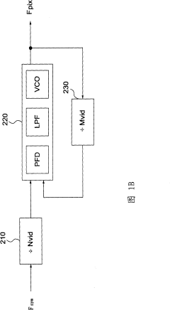
For example, the phase-locked loop 220 of the general receiving device 120 often prints Mvid, Nvid (or Maud, Naud) is much larger than the number of frequency dividers 210 and 230 (about 28), and it is easy to cause the frequency division to enter the phase frequency detector PFD The two divide-M and divide-N signals are only generated once for a long time, causing the output of the phase-locked loop 220 to jitter, and the above-mentioned frequency deviation phenomenon occurs; or DisplayPort has Support the design of spread spectrum, but also because of this, the Mvid or Maud received by the receiving device 120 may be a value with a large drift, then the receiving device 120 The pixel clock signal CLKpix restored according to this drift value is also prone to the above-mentioned frequency deviation phenomenon
As a result, an error occurs in the pixel clock signal CLKpix, which will cause the image format finally restored by the receiving device 120 to be different from the image format transmitted by the sending device 110, so that subsequent circuits (such as image scaling circuits ( scaler), display... and other devices) abnormal operation

Method used


Image

  • Receiving apparatus and clock signal rate calibration method
  • Receiving apparatus and clock signal rate calibration method
  • Receiving apparatus and clock signal rate calibration method

Examples


Embodiment Construction

[0038] The following description takes DisplayPort image data transmission as an example, but the technology of the present invention is not limited thereto, and can also be applied to DisplayPort audio data transmission or data transmission in other formats.

[0039] Figure 3A A block diagram of a DisplayPort receiving device 320 according to the present invention is shown. The receiving device 320 includes a physical layer (Physical layer) PHY and a link layer (Link layer) LINK.

[0040] The physical layer PHY uses a clock data recovery circuit (Clock Data Recovery, CDR) (not shown), connected to one of the data transmission channels of the main link, and restores the symbol clock signal CLK from the received image data sym '(and the actual symbol clock signal CLK of the sending device 110 sym comparison, there may be slight differences) and at the same time correctly receive the video data D sym . Afterwards, a decoder (not shown) is used again according to the symbol ...


PUM


Abstract

The invention provides a receiving device which comprises a buffer unit and a clock generating unit. The buffer unit receives decoding data, according to a symbol clock signal, reads the decoded data according to a pixel clock signal and generates a water level value. And the clock generating unit receives the symbol clock signal to generate a pixel clock signal, and adjusts the velocity of the pixel clock signal according to the water level value and / or a phase differential signal.

Description

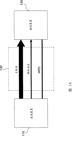
technical field [0001] The invention relates to video interface technology, in particular to a device applied to a receiving end of a display connection port (DisplayPort) interface. [0002] Background technique [0003] FIG. 1 is a schematic diagram of a display port (DisplayPort) interface connecting a source device (Source Device) and a sink device (Sink Device), and the interface. [0004] DisplayPort is a new generation of digital high-speed audio and video transmission interface promoted by Video electronics Standard Association (VESA). It uses PCI-EXRPESS type connection (Like Link) to carry video and audio data On the high-speed symbol clock signal (Symbol Clock Signal), and through the transmission of specific frequency ratio packets, the receiving end can restore the original image transmission rate and original sound transmission rate. [0005] Such as Figure 1A As shown, the DisplayPort interface 130 includes a main link (Main Link), an auxiliary channel (Aux...

Claims


Application Information

Patent Timeline
Patent Type & AuthorityPatents(China)
IPC IPC(8): G09G5/00
Inventor林佐柏龚文侠张贤钧
OwnerREALTEK SEMICON CORP