
Radar device

Inactive Publication Date: 2006-10-26
TDK CORPARATION
View PDF4 Cites 19 Cited by
  • Summary
  • Abstract
  • Description
  • Claims
  • Application Information

AI Technical Summary

Benefits of technology

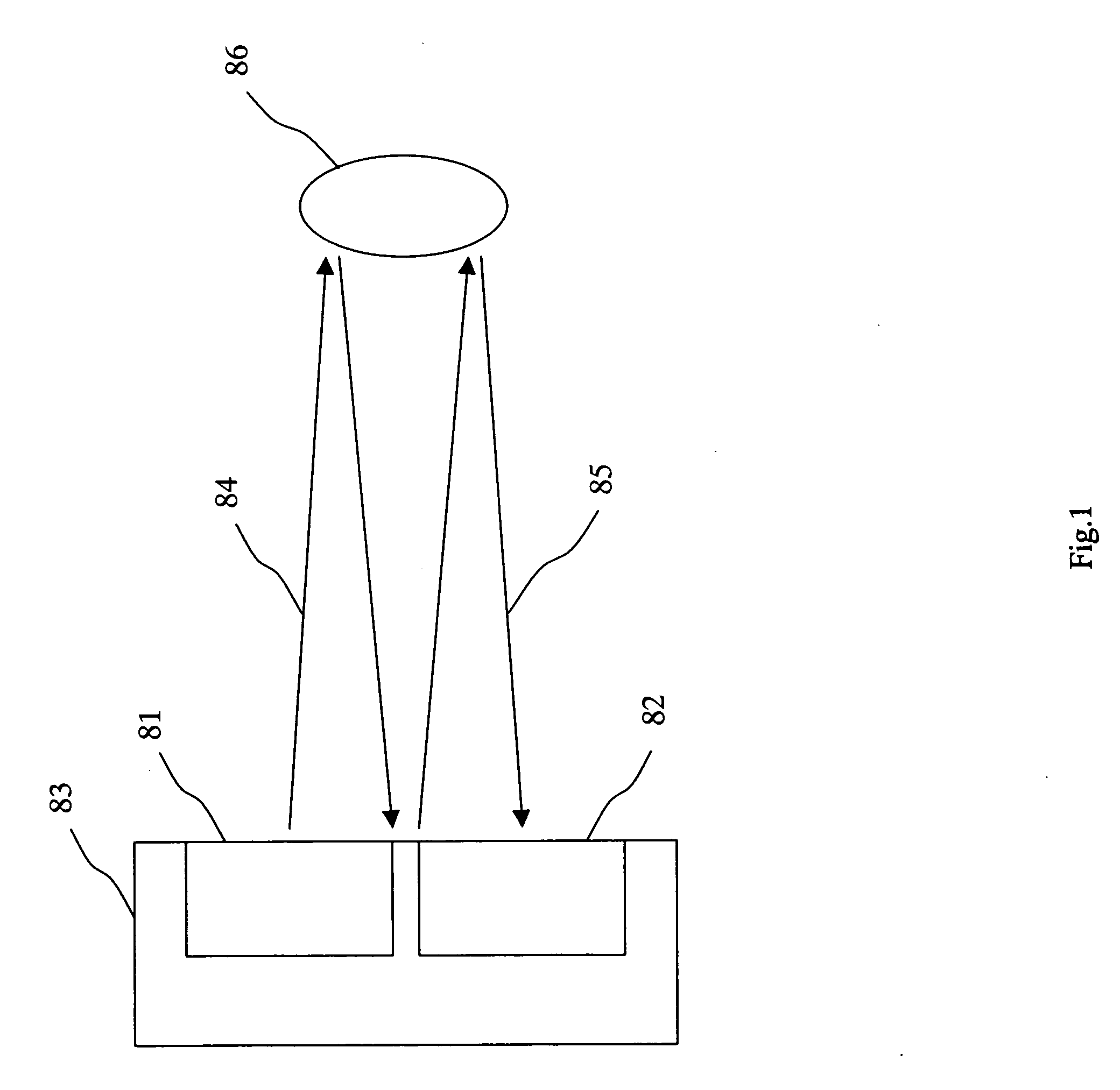
[0010] In view of the above problems, it is an object of the present invention to provide a radar device that can prevent multi-reflection to accurately measure a distance to a target at a short distance.
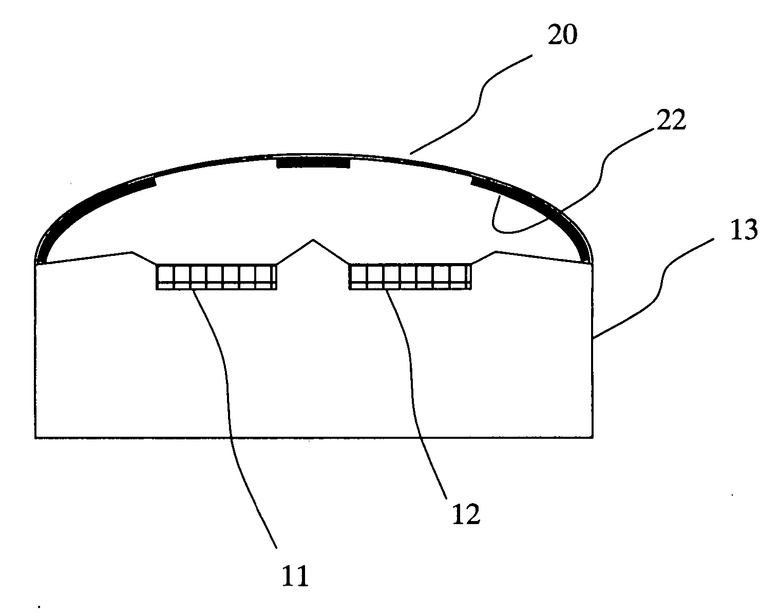
[0013] In the radar device according to the first aspect of the present invention, the surface of the frame body is diagonal to the plane that is perpendicular to the direction in which a transmitting wave is transmitted from the transmitting antenna, so that even if the transmitting wave transmitted from the transmitting antenna is reflected by a target, and the reflected wave is reflected again by the frame body, this twice-reflected wave can be prevented from being returned toward the target. Therefore there can be provided with a radar device which can measure a distance to the target accurately.
[0015] In the radar device according to the second aspect of the present invention, the frame body has a curved surface toward a direction in which a transmitting wave is transmitted from the transmitting antenna, so that even if the transmitting wave transmitted from the transmitting antenna is reflected by a target, and the reflected wave is reflected again by the frame body, this twice-reflected wave can be suppressed from being returned toward the target. Therefore there can be provided with a radar device which can measure a distance to the target accurately.
[0017] According to the present aspect, the electric wave absorber is attached to a part of the surface of the frame body, so that a transmitting wave transmitted from the transmitting antenna is reflected by a target and the reflected wave can be prevented from being returned toward the target. Therefore there can be provided with a radar device which can measure a distance to the target accurately.
[0019] According to the present aspect, the electric wave absorber is attached to the radome which covers the transmitting antenna and the receiving antenna, except the region that faces the transmitting antenna and the receiving antenna, it is possible to relax transmission and reflection of radio waves toward an undesired direction and reception of the radio waves from the undesired direction, thereby providing a radar device that can measure a distance to a target accurately.

Problems solved by technology

However, there are some cases where an echo removed by the signal processing may have been reflected by an actually existing target.
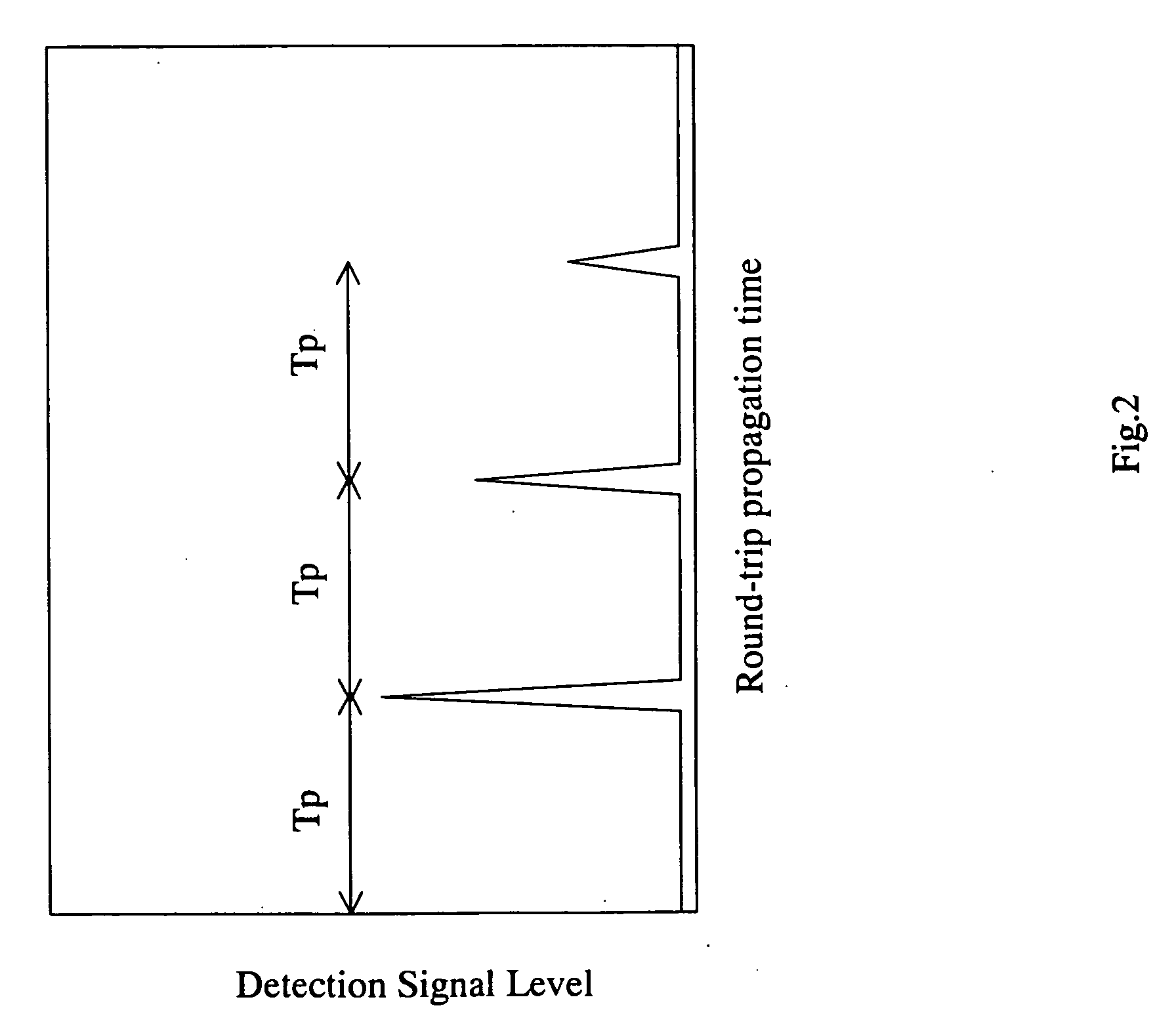
Therefore, it is difficult to decide whether an echo is formed by multi-reflecting or by reflecting from any other actual target, in the signal processing.
In particular, if a vehicle-installed radar device removes a reflected wave from a target that should exist originally, it is undesirable from a viewpoint of traffic safety.

Method used


Image

  • Radar device
  • Radar device
  • Radar device

Examples


Embodiment Construction

[0029] The following will describe embodiments of the present invention with reference to drawings. However, the present invention is not limited to the following embodiments.

[0030]FIG. 3 is an explanatory front view of one example of a radar device according to the present invention. FIG. 4 is a cross sectional view taken along line A-A′ of the radar device of FIG. 3. In FIGS. 3 and 4, numeral 11 indicates a transmitting antenna for transmitting a transmitting wave, numeral 12 indicates a receiving antenna for receiving a reflected wave, and numeral 13 indicates a frame body provided around the transmitting antenna 11 and the receiving antenna 12. FIG. 4 does not show a driver circuit for driving the transmitting antenna, a reception circuit for amplifying a receiving wave from the receiving antenna, and the like.

[0031] The frame body 13 will support the transmitting antenna 11 and the receiving antenna 12 and suppresses a radio wave from leaking to the receiving antenna 12 from ...


PUM


Abstract

A radar device which is installed in a vehicle or the like needs to detect a target at a short distance from several tens of centimeters to several tens of meters and, therefore, has a problem that a reflected wave from the target may be reflected by a front case of the radar device and then reflected by the target again to be received as a secondary echo by itself. To solve this problem, it is an object of the present invention to provide a radar device again that can prevent multi-reflection to accurately measure a distance to a target in a short range. In a radar device according to the present invention, a surface of a frame body provided around a transmitting antenna and a receiving antenna is shaped so that a reflected wave from a target may not be returned in a direction in which a transmitting wave is transmitted from the transmitting antenna.

Description

BACKGROUND OF THE INVENTION [0001] 1. Field of the Invention [0002] The present invention relates to a radar device which prevents multi-reflection of a reflection wave from a target at a short distance. [0003] 2. Description of the Related Art [0004] Recently, a radar device is installed in a vehicle for a purpose of collision prevention or auto-cruise. In such a vehicle-installed radar device, a round-trip distance to a target is obtained by integrating a light velocity over a lapse of time from a point in time when a pulse transmitting wave is transmitted to a point in time when a reflected wave from the target is received, so that the lapse of time from the moment of transmission of the pulse transmitting wave to the moment of reception of the reflected wave from the target is measured to thereby calculate the distance to the target. [0005] After having transmitted a transmitting pulse wave, such a radar device prepares for receiving of a receiving pulse wave reflected from a ta...

Claims


Application Information

Patent Timeline
IPC IPC(8): G01S7/28H01Q17/00H01Q1/42G01S13/931
CPCG01S7/032G01S13/931H01Q17/004H01Q1/521H01Q1/42
Inventor IKEDA, HIROSHI
Owner TDK CORPARATION
Learn More