Display apparatus

a technology of display apparatus and display screen, which is applied in the field of display screen, can solve problems such as distortion of the projected image of the object, and achieve the effects of improving usefulness, high distance measurement accuracy, and improving distance measurement accuracy

Active Publication Date: 2010-04-01
MARVELL INT LTD +1
View PDF2 Cites 25 Cited by
  • Summary
  • Abstract
  • Description
  • Claims
  • Application Information

AI Technical Summary

Benefits of technology

[0045]The first measuring device implements one of so-called light flight time measuring methods capable of measuring a light flight time, or a distance to a projected image reception object. The accuracy of an average value, i.e., the distance measuring accuracy can be improved by increasing the number of reflections. That is, for a frequency that provides a resolution capability required by a desired measuring accuracy, a substantially lower frequency can be used for the reference clock. Thus it is possible to build a measuring device with a high distance measuring precision using an inexpensive circuit system.
[0046]With this invention, when projecting a video onto a curved surface for display, it is possible to realize an undistorted display of the video, allowing for an improved usefulness and a wider range of use of the display apparatus.

Problems solved by technology

However, when an image is actually projected onto the undulated or uneven surface of an object, the projected image on the object may get distorted because of differences of degrees of such undulation or unevenness over the recessed and protruding surfaces of the object.

Method used


Image

  • Display apparatus
  • Display apparatus
  • Display apparatus

Examples


embodiment 1

[0057]In describing an example embodiment of the display apparatus, an embodiment of a measuring device will be first explained.

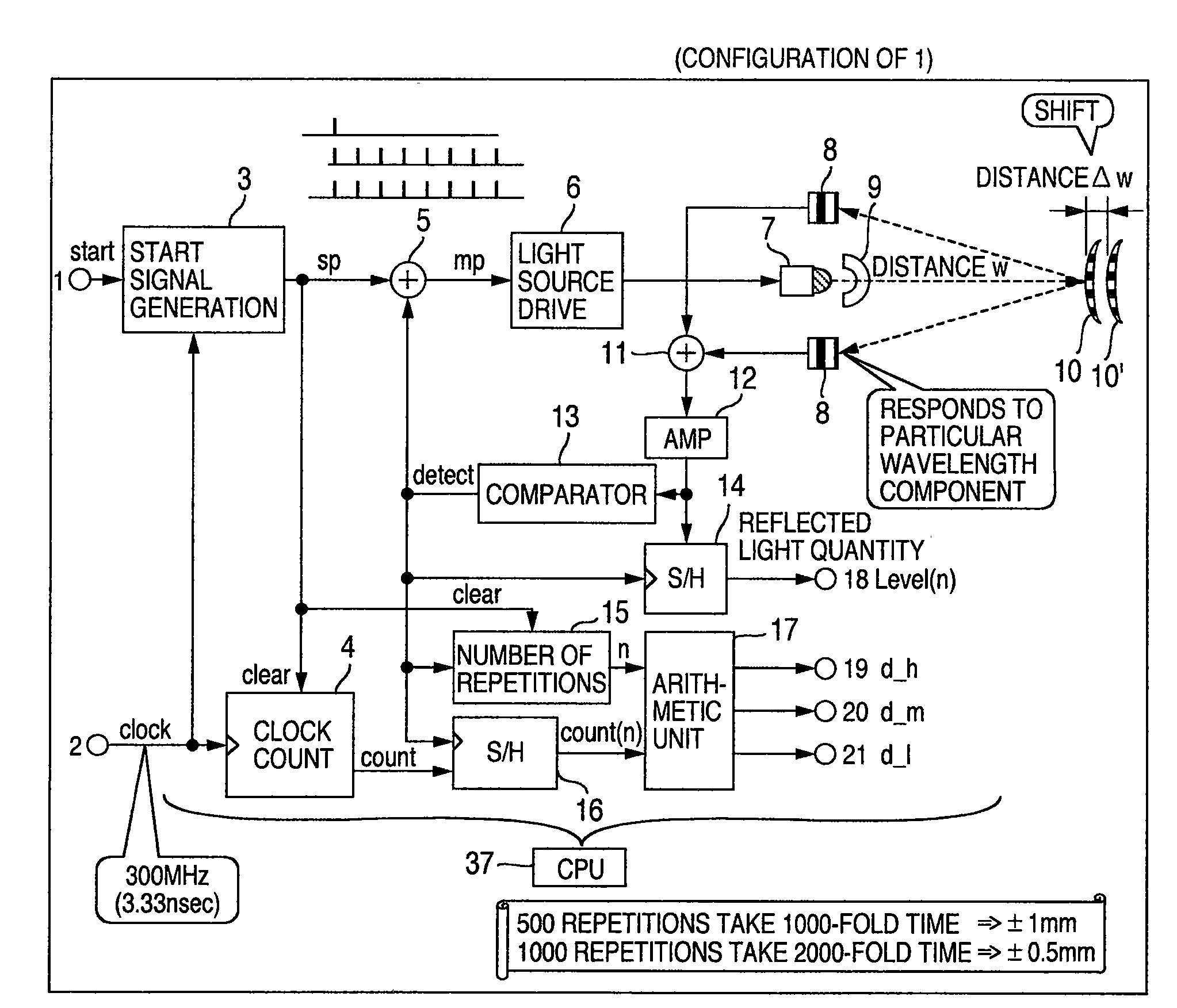
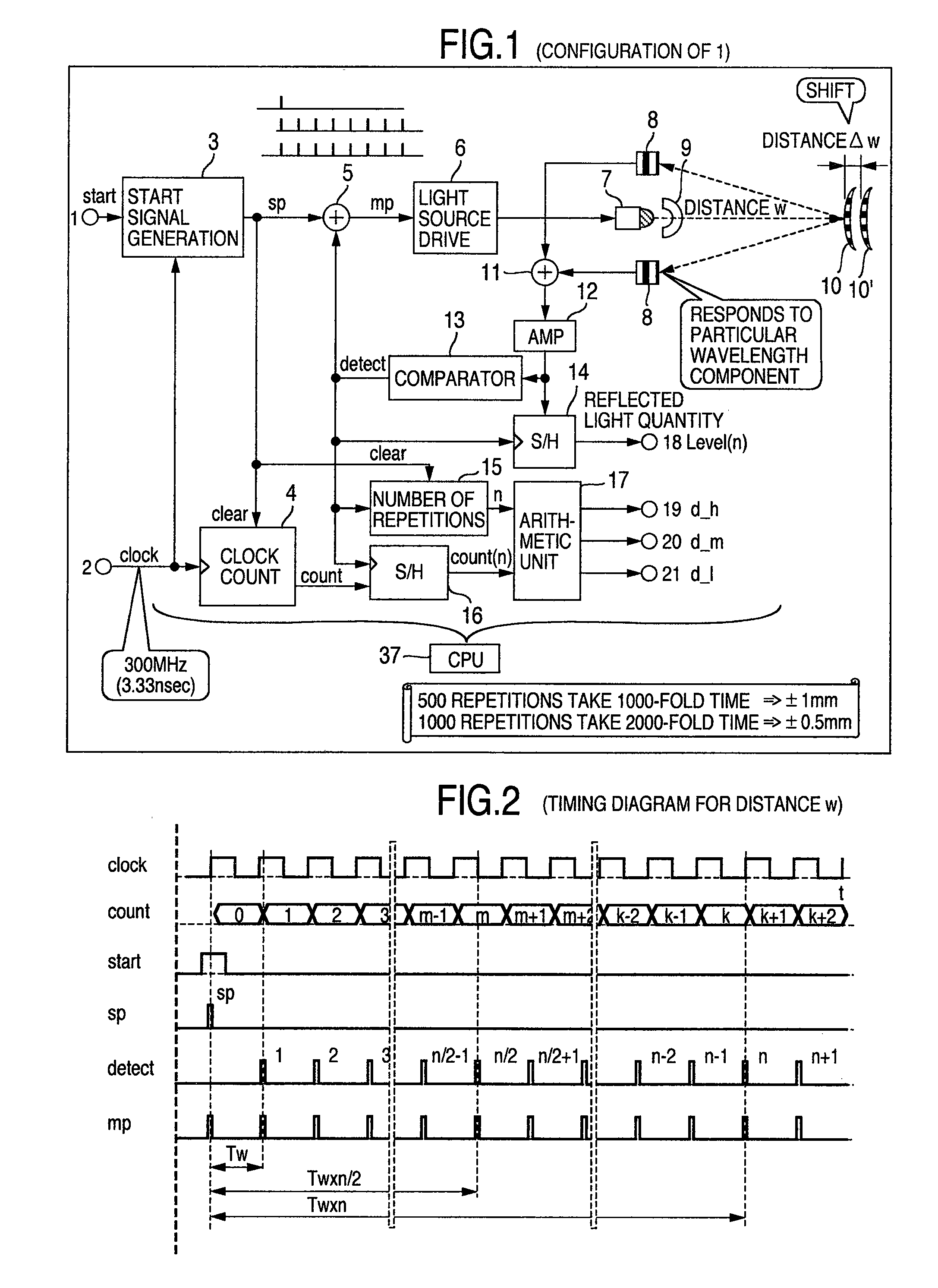
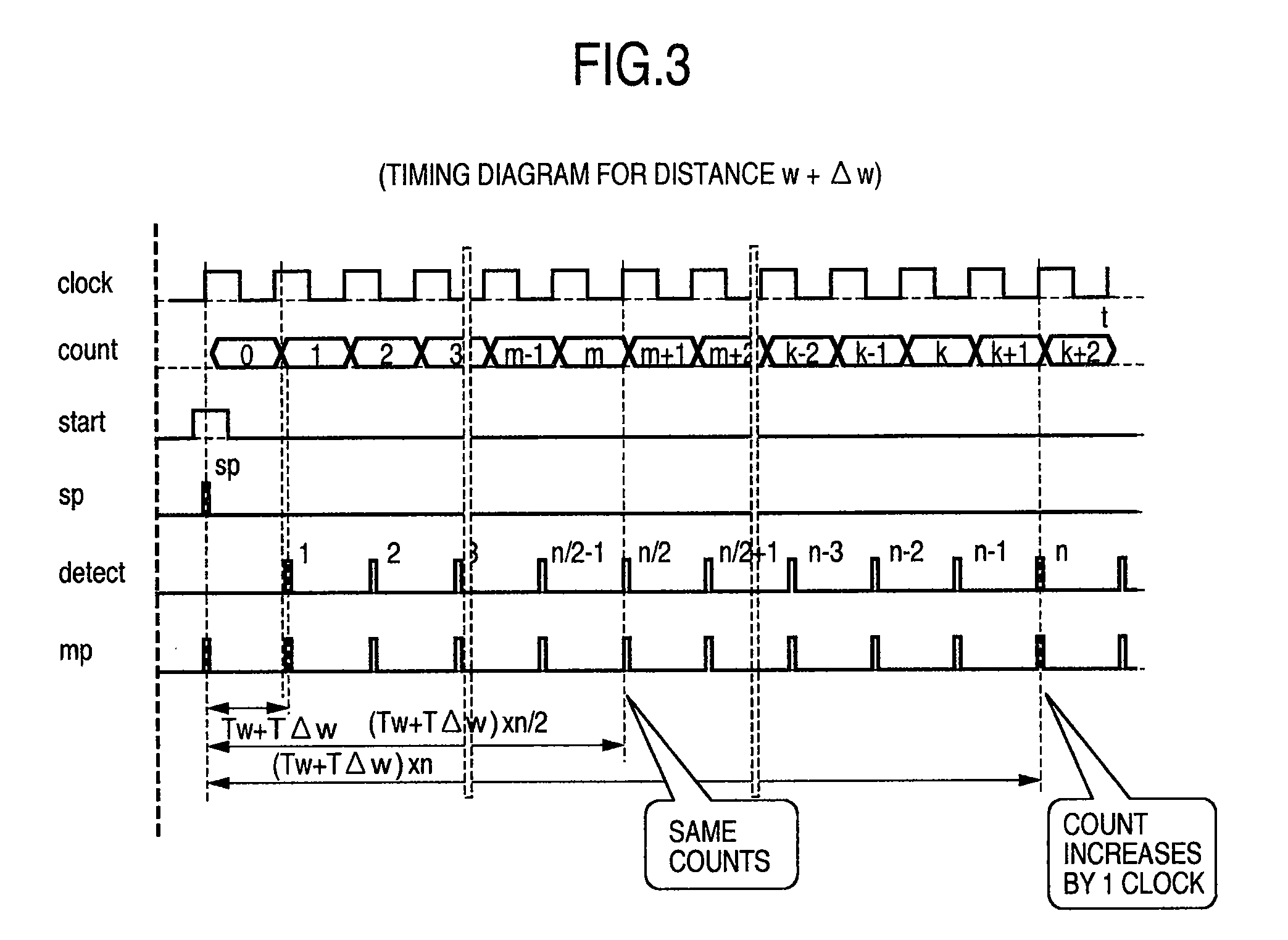
[0058]FIG. 1 is a block diagram showing the measuring device of the first embodiment of this invention. FIG. 2 and FIG. 3 are timing diagrams at a measuring distance w and a measuring distance w+Δw.

[0059]In FIG. 1, denoted 1 is a start signal START, 2 a reference clock CLOCK, 3 a start signal generation circuit, 4 a clock counter, 5 a timing signal adder, 6 a light source drive circuit, 7 a light source, 8 a plurality of light amount detection units, 9 a collimate lens, 10 and 10′ objects to be measured, 11 a detected light amount, or quantity adder, 12 a signal amplifier AMP, 13 a comparator, 14 a reflected light quantity sample-hold circuit, 15 a reflection counter, 16 a count value sample-hold circuit, 17 an arithmetic unit, 18 reflected amount information, and 19, 20, 21 pieces of distance information d_h, d_m, d_l with different detection precisions. D...

embodiment 2

[0088]FIG. 4 is a block diagram showing a display apparatus according to a second embodiment of this invention.

[0089]In FIG. 4, designated 22 is a horizontal synchronization signal (Hsync), 23 a vertical synchronization signal (Vsync), 24 a video signal, 25 a pixel address generation unit, 26 a horizontal / vertical oscillation drive unit, 27 a reflection mirror composed of a horizontal oscillation unit, 28 a vertical oscillation unit, and 29 an object onto which an image is to be projected.

[0090]FIG. 5 shows how a beamlike light flux emitted from the light source 7 and reflected by the reflection mirror 27 oscillating on two axes, scans over the object and how the projected beam is reflected from the object and returns to the light quantity detection units 8. Denoted 30 is a trace of a beam of light, and 31 an effective display area.

[0091]FIG. 6 and FIG. 7 show operation timing diagrams for a distance w and a distance w+Δw.

[0092]This embodiment is not concerned with the shape of the ...

embodiment 3

[0104](Third Display Apparatus)

[0105]FIG. 8 is a block diagram showing a display apparatus of the third embodiment of this invention. What is shown in FIG. 8 is comprised of the measuring device and the display apparatus described in the first and second embodiment of this invention. The third embodiment is characterized in that there are at least as many light sources 7 as three primary colors of R / G / B and that the light source drive circuit 6 drives the individual R / G / B light sources 7 independently or simultaneously in a way similar to the above. FIG. 9 shows the configuration of the image distortion correction circuit of the third embodiment, which is the same as that of the second embodiment, except that the light quantity detection units 8 not only detect the intensities of R / G / B light components but also distinguish them. The light quantity detection units 8 may of course be constructed to detect only the light intensities. With the above display apparatus of the third embodi...


PUM


Abstract

A display apparatus is provided which, when projecting a video onto a curved surface of an object for display, can realize an undistorted display of the video. The measuring means outputs the distance information representing the distance to the object. Based on the distance information produced by the measuring means, the curved surface contour is detected with high precision. According to at least the detected curved surface contour distortions, pixels of the display image are unevenly rearranged to correct the video information before it is output. This arrangement realizes an undistorted display of video when the video is projected onto the curved surface of the object.

Description

INCORPORATION BY REFERENCE[0001]The present application claims priority from Japanese application JP2008-249507 filed on Sep. 29, 2008, the content of which is hereby incorporated by reference into this application.BACKGROUND OF THE INVENTION[0002]The present invention relates to a display apparatus that projects vibrating beams of light onto an object to form a video image thereon.[0003]Conventional projection devices use a projection lens to project a video onto an object such as a screen or the like.[0004]Under these circumstances, a display apparatus using MEMS (Micro Electro Mechanical Systems) devices and laser beams has come to be known and is disclosed in JP-A-2006-343397 (page 10, FIG. 1).[0005]There have been proposed many kinds of measuring methods and devices. Among the methods using beams a light pulse flight hour measuring method is known. With both advancement of technologies in such MEMS field, semiconductor laser field or the like and reductions in product size or c...

Claims


Application Information

Patent Timeline
Patent Type & Authority Applications(United States)
IPC IPC(8): H04N9/31
CPCH04N9/3129H04N9/3194H04N9/3185
Inventor KOBORI, TOMOKIOUCHI, SATOSHIHIRATA, KOJIIKEDA, HIDEHIROSHIKITA, KAZUO
Owner MARVELL INT LTD
Why Eureka
Try Eureka