Method for measuring fault location of HVDC (High Voltage Direct Current) transmission line under consideration of measured wave velocity
A transmission line, high-voltage DC technology, applied in directions such as fault locations, can solve problems such as low ranging accuracy
- Summary
- Abstract
- Description
- Claims
- Application Information
AI Technical Summary
Problems solved by technology
Method used
Image
Examples
Embodiment
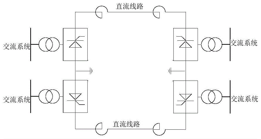
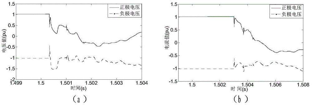
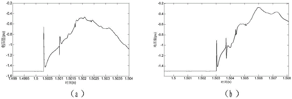
[0171] A typical calculation example of a single-pole ground fault is selected: the simulation model is as follows figure 1 As shown in , set a single-pole ground fault at 100km away from the rectifier side of the DC line, and the transition resistance is 0Ω. The voltage data obtained by the measuring devices at both ends are as follows: figure 2 shown. The fault voltage data is filtered by the alternating hybrid filter of mathematical morphology, so that the phase-mode transformation is performed on the filtered fault voltage data to obtain a linear-mode traveling wave, as shown in image 3 . Decompose the line-mode voltage through EEMD to obtain its intrinsic mode function (IMF), and perform Hilbert transformation on the high-frequency component IMF1 to obtain its time-frequency diagram, as shown in Figure 4 shown. pass Figure 4 It can be determined that the moment when the fault initial traveling wave reaches the rectifier side is 1.500336s and its corresponding inst...
PUM
 Abstract
Description
Claims
Application Information
 - R&D
- Intellectual Property
- Life Sciences
- Materials
- Tech Scout
- Unparalleled Data Quality
- Higher Quality Content
- 60% Fewer Hallucinations
Browse by: Latest US Patents, China's latest patents, Technical Efficacy Thesaurus, Application Domain, Technology Topic, Popular Technical Reports.
© 2025 PatSnap. All rights reserved.Legal|Privacy policy|Modern Slavery Act Transparency Statement|Sitemap|About US| Contact US: help@patsnap.com


