Cloth attaching machine

An applicator and applicator technology, applied in nonlinear optics, instruments, optics, etc., can solve problems such as poor adhesion, waste of double-sided tape and friction cloth, time-consuming and labor-intensive, and solve errors and inconsistencies. , the effect of improving quality and life, reducing production costs

Active Publication Date: 2014-09-03
HEFEI XINSHENG OPTOELECTRONICS TECH CO LTD +1
View PDF5 Cites 17 Cited by
  • Summary
  • Abstract
  • Description
  • Claims
  • Application Information

AI Technical Summary

Problems solved by technology

[0005] In the prior art cloth applicator, the relative positions of the rollers, double-sided tape and friction cloth are roughly positioned manually. Due to the errors and inconsistencies of manual operations, the alignment is not accurate enough, which affects the quality of the rolls and is time-consuming. power, inefficiency;
[0006] The double-sided adhesive tape and rubbing cloth are laid flat on the abutment, which requires manual pulling to achieve the leveling and alignment of the rubbing cloth, which will easily cause the hair of the rubbing cloth to fall off, causing pollution to the rubbing process and reducing the quality of the process;
[0007] Moreover, in the process of patching and gluing, the friction cloth and double-sided adhesive are laid on the abutment, and as the rollers roll, the friction cloth and double-sided adhesive will be offset to a certain extent, resulting in poor adhesion, resulting in The waste of double-sided tape and friction cloth increases production costs;
[0008] In addition, the abutment cannot be flexibly translated and rotated. In some processes, double-sided adhesive tape and friction cloth need to be rotated at a certain angle for patching. Existing patching machines cannot accurately meet this requirement

Method used


Image

  • Cloth attaching machine
  • Cloth attaching machine
  • Cloth attaching machine

Examples


Embodiment Construction

[0050] The principles and features of the present invention are described below in conjunction with the accompanying drawings, and the examples given are only used to explain the present invention, and are not intended to limit the scope of the present invention.

[0051] Aiming at the problem of large alignment errors and low efficiency in the prior art that requires manual alignment, the present invention provides a cloth applicator that can realize automatic and accurate alignment, improve alignment accuracy, and improve production efficiency.

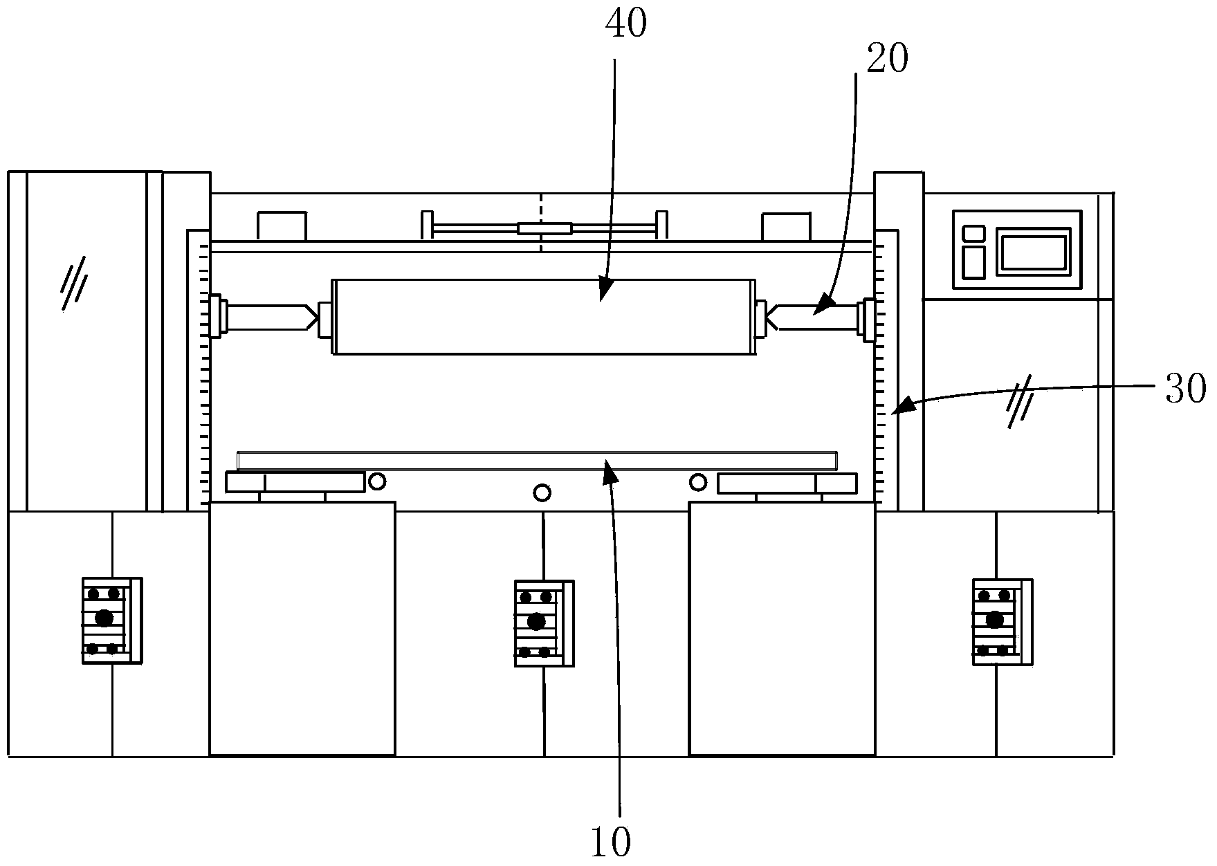
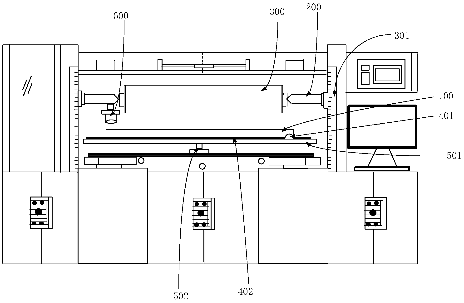
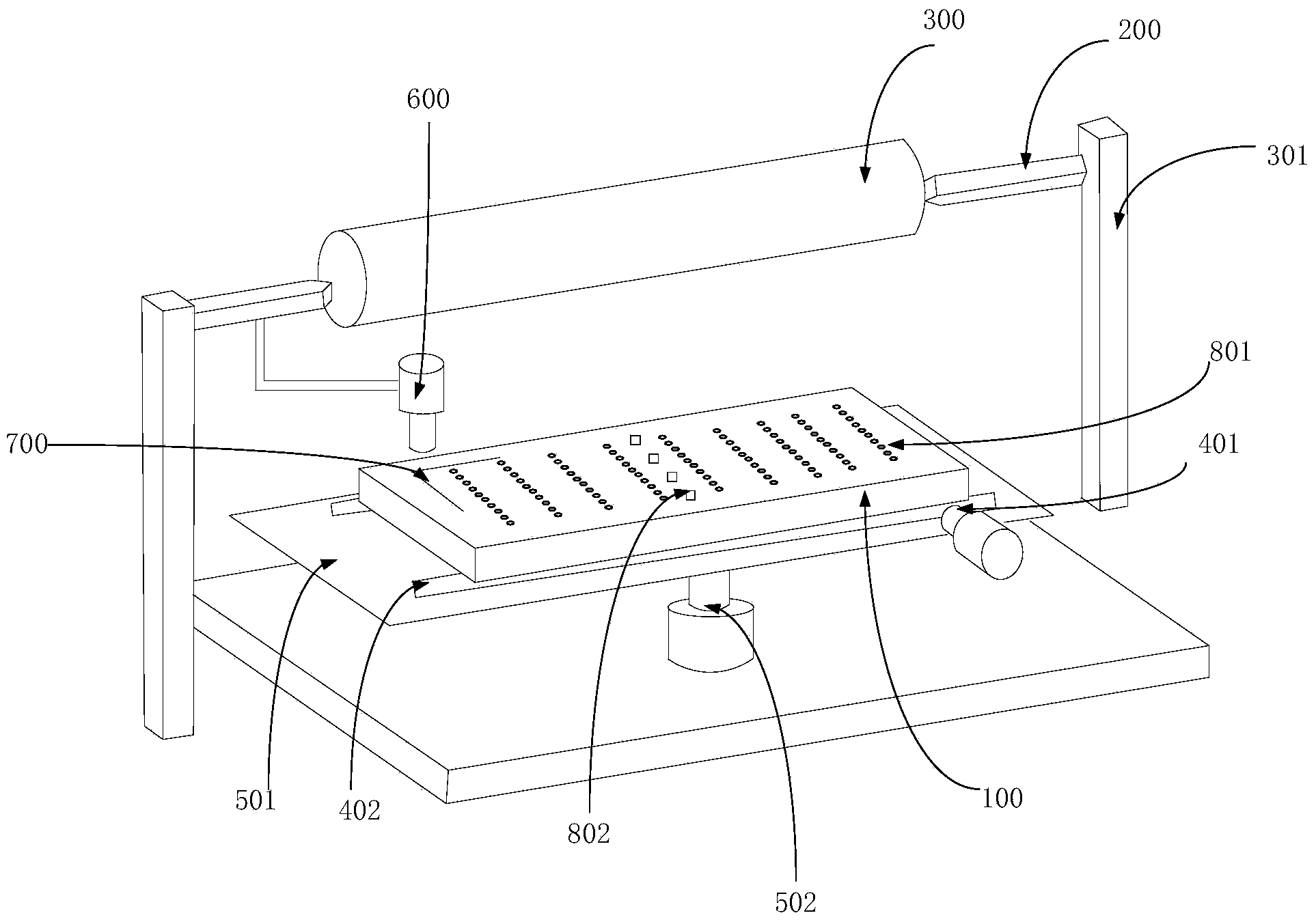
[0052] like figure 2 and image 3 As shown, the patching machine provided by the present invention includes:

[0053] The movable abutment 100 is used to place friction cloth and double-sided tape;

[0054] The movable clamping mechanism 200 is arranged above the base 100, and is used to clamp and fix the roller 300 to be pasted;

[0055] The roller driving mechanism 301 is used to move the clamping mechanism 200 to move the rol...


PUM


Abstract

The invention provides a cloth attaching machine. The cloth attaching machine comprises a movable base station, a movable clamping mechanism, a roller driving mechanism, a base station driving mechanism, a detection mechanism and a control mechanism, wherein the movable base station is used for containing friction cloth and double faced adhesive tape, the movable clamping mechanism is arranged above the base station and used for clamping and fixing a roller to which the cloth needs to be attached, the roller driving mechanism is used for moving the clamping mechanism, the base station driving mechanism is used for moving the base station, the detection mechanism is used for detecting the position, relative to the roller, of the friction cloth and the position, relative to the roller, of the double faced adhesive tape, and the control mechanism is used for controlling the base station driving mechanism and the roller driving mechanism to move the base station and the clamping mechanism respectively according to a detection result of the detection mechanism, so that the friction cloth, the double faced adhesive tape and the roller are made to move to be aligned. According to the cloth attaching machine, automatic precise alignment can be achieved, the problem that in the prior art, errors and inconsistency exist when alignment is conducted manually, roller manufacturing efficiency is improved, and the quality of the friction roller is improved.

Description

technical field [0001] The invention relates to the field of display technology, in particular to a patching machine. Background technique [0002] The rubbing process in the liquid crystal panel box forming process refers to rubbing the surface of the alignment film on the array substrate and the color filter substrate in a certain direction with nylon cloth, fiber or cotton cloth, so as to form grooves for liquid crystals to be arranged at a pre-tilt angle. The process is called liquid crystal molecular alignment technology. The quality of the alignment effect has an important impact on the basic properties of the liquid crystal display, such as uniformity, viewing angle, color difference, response speed, and threshold voltage. The quality of the orientation effect is inseparable from the quality of the rubbing roller, so the technology or method of making the roller is very important for the rubbing process. [0003] figure 1 Shown is a structural schematic diagram of ...

Claims


Application Information

Patent Timeline
Patent Type & Authority Applications(China)
IPC IPC(8): G02F1/1337
Inventor 余鹏于德董家勇王文浩
Owner HEFEI XINSHENG OPTOELECTRONICS TECH CO LTD
Why Eureka
Try Eureka