Semiconductor device, manufacturing method, and electronic device

a semiconductor and manufacturing method technology, applied in the field of semiconductor devices, can solve the problems of inability to put the electric field effect transistor into practical use, and the active layer may be wholly blocked, so as to reduce the manufacturing cost facilitate the manufacture of the semiconductor device, and stabilize the element property of the semiconductor device.

Active Publication Date: 2006-11-02
SHARP KK +2
View PDF10 Cites 4326 Cited by
  • Summary
  • Abstract
  • Description
  • Claims
  • Application Information

AI Technical Summary

Benefits of technology

[0041] It is preferable to arrange the semiconductor device such that: a blocking layer constituting the blocking layers is made of SiO2, Al2O3, AlN, MgO, Ta2O5, TiO2, ZrO2, stab-ZrO2, CeO2, K2O, Li2O, Na2O, Rb2O, In2O3, La2O3, Sc2O3, Y2O3, KNbO3, KTaO3, BaTiO3, CaSnO3, CaZrO3, CdSnO3, SrHfO3, SrSnO3, SrTiO3, YScO3, CaHfO3, MgCeO3, SrCeO3, BaCeO3, SrZrO3, BaZrO3, LiGaO2, a mixed crystal of LiGaO2 such as (Li1−(x+y)NaxKy)(Ga1-zAlz)O2, or a solid solution containing at least two of them, and the blocking layer is so provided as to meet the active layer separately from (i) each of two electrodes serving as blocking layers and connected to the active layer, and (ii) an insulating layer, which serves as a blocking layer and meets the active layer, for insulating the active layer from a control electrode for controlling move of a movable electric charge in the active layer. The two electrodes connected to the active layer correspond to, e.g., a source electrode and a drain electrode of a thin film transistor, respectively. Moreover, the control electrode corresponds to a gate electrode thereof. In an inverse-staggered thin film transistor, a gate electrode is formed on a substrate. Formed on the gate electrode is a gate insulating layer (blocking layer). On the gate insulating layer, the active layer is formed. The blocking layer meeting the active layer separately from the gate insulating layer is such a blocking layer (corresponding to the protective layer 8 shown in FIG. 1(a) through FIG. 1(c)) that meets (i) the upper end surface of the active layer, and (ii) a part of the side end surface thereof. The upper end surface of the active layer refers to a surface positioned between the source electrode and the drain electrode. As such, the structure is provided with the blocking layer which is provided separately from the electrodes and the insulating layer each required for such a semiconductor device, and which serves as a protective layer for blocking the active layer from the atmosphere. Moreover, the blocking layer directly meeting the above region is made of each of the aforementioned materials that match well with the ZnO and the MgxZn1-xO as described above. This makes it possible to stabilize the element property of the semiconductor device.
[0042] It is preferable to arrange the semiconductor device such that at least one of the blocking layers is made of resin. A blocking layer made of resin can be formed with the use of an existing resin formation device. Accordingly, a complex film formation process is not required for the formation of the blocking layer. This makes it easier to manufacture the semiconductor device. This allows reduction of manufacturing cost of the semiconductor device. Further, the use of the resin allows improvement of flexibility of the semiconductor device. This is especially suitable in cases where a flexible substrate is used as the substrate of the semiconductor device.
[0043] It is preferable to arrange the semiconductor device such that: a blocking layer constituting the blocking layers is made of resin, and the blocking layer is so provided as to meet the active layer separately from (i) each of two electrodes serving as blocking layers and connected to the active layer, and (ii) an insulating layer, which serves as a blocking layer and meets the active layer, for insulating the active layer from a control electrode for controlling move of a movable electric charge in the active layer. The two electrodes connected to the active layer correspond to, e.g., a source electrode and a drain electrode of a thin film transistor, respectively. Moreover, the control electrode corresponds to a gate electrode thereof. In an inverse-staggered thin film transistor, the blocking layer meeting the active layer separately from the gate insulating layer is such a blocking layer (corresponding to the protective layer 8 shown in FIG. 1(a) through FIG. 1(c)) that meets (i) the upper end surface of the active layer, and (ii) a part of the side end surface thereof, as described above. The upper end surface of the active layer refers to a surface positioned between the source electrode and the drain electrode. As such, the structure is provided with the blocking layer which is provided separately from the electrodes and the insulating layer each required for such a semiconductor device, and which serves as a protective layer for blocking the active layer from the atmosphere. Moreover, the blocking layer directly meeting the region can be made of a resin. This makes it possible to reduce the manufacturing cost of the semiconductor device as described above.
[0044] An electronic device of the present invention includes, as a switching element, any one of the semiconductor devices described above. A performance of the electronic device can be improved by the high performance semiconductor device which uses the transparent ZnO and MgxZn1-xO for the active layer, and which is provided as the switching element.
[0045] It is preferable to arrange the electronic device such that the switching element is connected to a picture element electrode such that an image signal is written in or read out from the picture element electrode. In an active matrix type display device (e.g., a liquid crystal display device or an organic EL display device) serving as the electronic device, the switching element is turned ON when the image signal is supplied from a driving circuit to the picture element electrode. Further, in an image sensor serving as the electronic device, the switching element is turned ON when reading out the image signal captured in the picture element electrode. As such, the semiconductor device can be used as the switching element in the image displaying electronic device or the image capturing electronic device. This makes it possible for such electronic devices to have high performance with ease.

Problems solved by technology

For this reason, such an electric field effect transistor cannot be put into practical use.
Further, the active layer may be wholly blocked by the blocking member.

Method used


Image

  • Semiconductor device, manufacturing method, and electronic device
  • Semiconductor device, manufacturing method, and electronic device
  • Semiconductor device, manufacturing method, and electronic device

Examples


embodiment 1

[0085] Embodiment 1 of the present invention will be explained below with reference to FIG. 1 through FIG. 5.

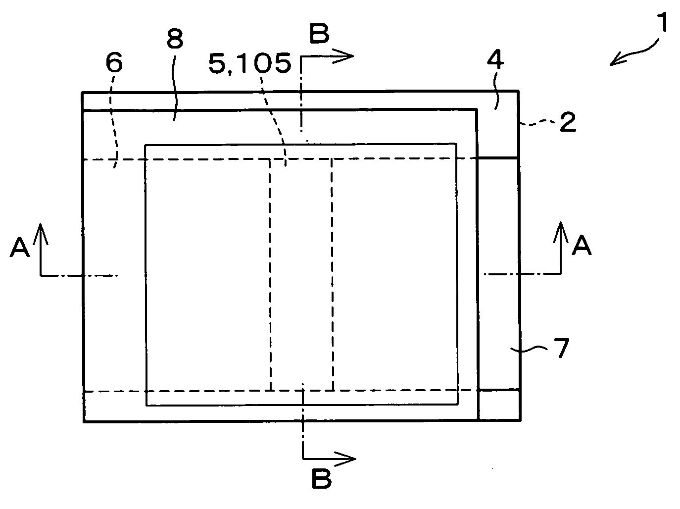
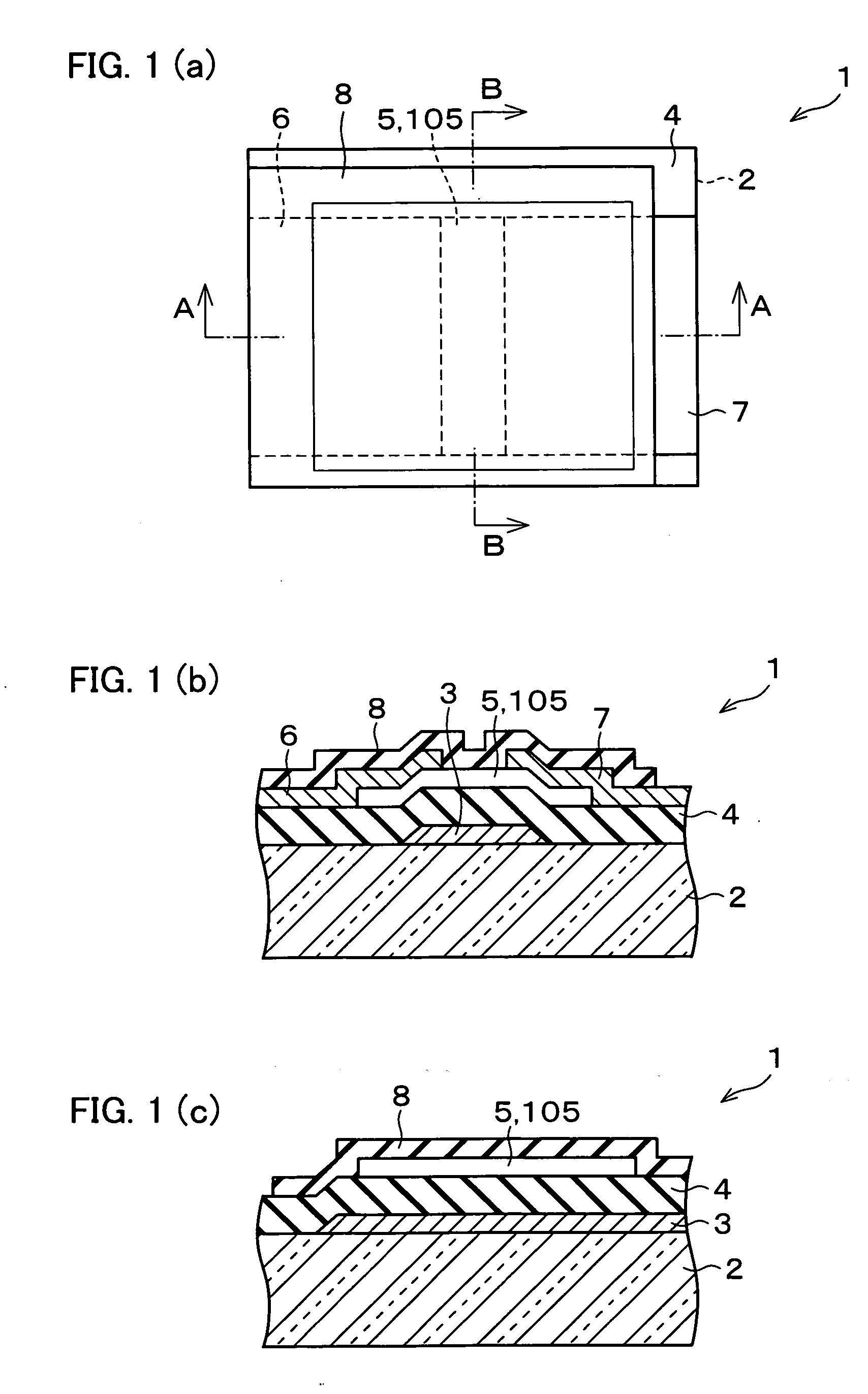
[0086]FIG. 1(a) is a plan view illustrating a thin film transistor 1 according to the present embodiment. FIG. 1(b) is a cross sectional view taken along line A-A of FIG. 1(a). FIG. 1(c) is a cross sectional view taken along line B-B of FIG. 1(a). Note that, although FIG. 1(b) and FIG. 1(c) describes rise and recess each formed in the central portion of the surface of a protective layer 8, FIG. 1(a) does not describe the rise and the recess for the sake of simplicity.

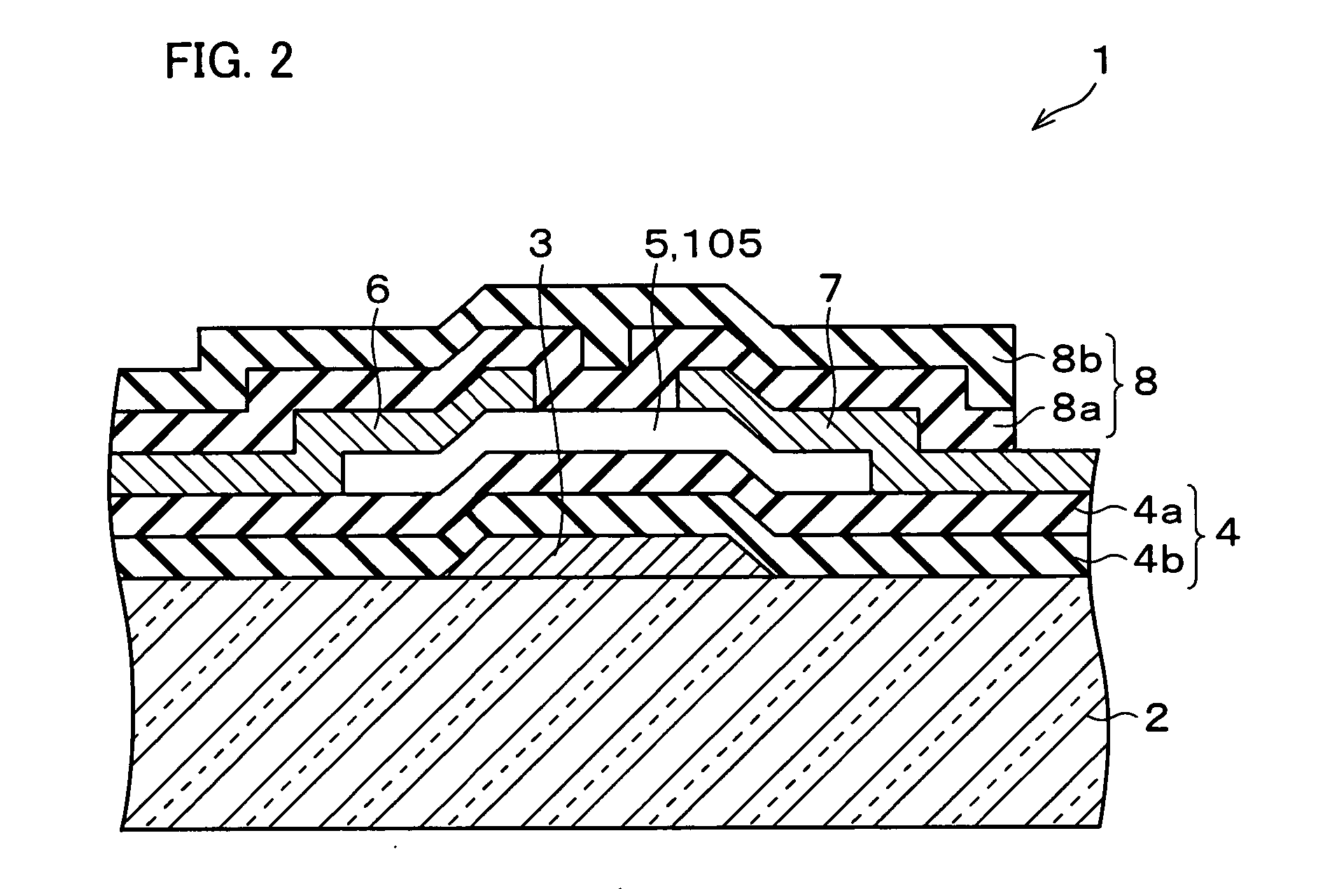
[0087] As shown in FIG. 1(a) through FIG. 1(c), the thin film transistor 1 serving as a semiconductor device has the inverse staggered structure. Specifically, a gate electrode 3 is formed on an insulating substrate 2. On the insulating substrate 2 and the gate electrode 3, a gate insulating layer 4 is provided. Provided on the gate insulating layer 4 is a semiconductor layer 5. Provided on the semiconductor la...

embodiment 2

[0107] Embodiment 2 of the present invention will be explained below with reference to FIG. 6 through FIG. 8.

[0108]FIG. 6(a) is a plan view illustrating a thin film transistor 11 according to the present embodiment. FIG. 6(b) is a cross sectional view taken along line C-C of FIG. 6(a). FIG. 6(c) is a cross sectional view taken along line D-D of FIG. 6(a). Note that, although FIG. 6(b) and FIG. 6(c) describes rise and recess each formed in the central portion of the surface of a protective layer 19, FIG. 6(a) does not describe the rise and the recess for the sake of simplicity.

[0109] As shown in FIG. 6(a) through FIG. 6(c), the thin film transistor 11 serving as a semiconductor device has the staggered structure. Specifically, a priming insulating layer 13 is formed on an insulating substrate 12. A source electrode 14 and a drain electrode 15 are formed on the priming insulating layer 13 with a space therebetween. Formed on and above the source electrode 14, the drain electrode 15,...

embodiment 3

[0132] Embodiment 3 of the present invention will be described below with reference to FIG. 9 through FIG. 11.

[0133]FIG. 9(a) is a plan view illustrating a thin film transistor 21 according to the present embodiment. Further, FIG. 9(b) is a cross sectional view taken along line E-E of FIG. 9(a). FIG. 9(c) is a cross sectional view taken along line F-F of FIG. 9(a).

[0134] As shown in FIG. 9(a) through FIG. 9(c), the thin film transistor 21 serving as a semiconductor device is arranged as follows. That is, a priming insulating layer 23 is formed on an insulating substrate 22. Formed on the priming insulating layer 23 are a source electrode 24 and a drain electrode 25. Further, a semiconductor layer 26 is formed on the priming insulating layer 23, the source electrode 24, and the drain electrode 25. Formed on the semiconductor layer 26 is a first gate insulating layer 27. The semiconductor layer 26 and the first gate insulating layer 27 are covered with a second gate insulating layer...


PUM


Abstract

In a thin film transistor (1), a gate insulating layer (4) is formed on a gate electrode (3) formed on an insulating substrate (2). Formed on the gate insulating layer (4) is a semiconductor layer (5). Formed on the semiconductor layer (5) are a source electrode (6) and a drain electrode (7). A protective layer (8) covers them, so that the semiconductor layer (5) is blocked from an atmosphere. The semiconductor layer (5) (active layer) is made of, e.g., a semiconductor containing polycrystalline ZnO to which, e.g., a group V element is added. The protective layer (8) thus formed causes decrease of a surface level of the semiconductor layer (5). This eliminates a depletion layer spreading therewithin. Accordingly, the ZnO becomes an n-type semiconductor indicating an intrinsic resistance, with the result that too many free electrons are generated. However, the added element works on the ZnO as an accepter impurity, so that the free electrons are reduced. This decreases a gate voltage required for removal of the free electrons, so that the threshold voltage of the thin film transistor (1) becomes on the order of 0V. This allows practical use of a semiconductor device which has an active layer made of zinc oxide and which includes an protective layer for blocking the active layer from an atmosphere.

Description

TECHNICAL FIELD [0001] The present invention relates to a semiconductor device having an active layer made of a zinc oxide. The present invention particularly relates to (i) a semiconductor device suitable for a switching element for use in an electronic device, and (ii) an electronic device using the semiconductor device. BACKGROUND ART [0002] Conventionally, zinc oxide (ZnO) is transparent in a visible light region, and is a semiconductor having a relatively good property even when prepared under a low temperature. For this reason, study on ZnO has been actively carried out in recent years, so that various techniques have been reported. [0003] For example, see Documents 1 through 3 of scientific papers. Each of the scientific papers teaches that a thin film transistor having an active layer made of ZnO operates with high performance. [0004] (1) Document 1: [0005] R. L. Hoffman, B. J. Norris and J. F. Wager, “ZnO-based transparent thin-film transistors” APPLIED PHYSICS LETTERS VOLU...

Claims


Application Information

Patent Timeline
Patent Type & Authority Applications(United States)
IPC IPC(8): H01L23/58H01L21/336H01L29/786
CPCH01L29/66969H01L29/7869
Inventor SUGIHARA, TOSHINORIOHNO, HIDEOKAWASAKI, MASASHI
Owner SHARP KK
Why Eureka
Try Eureka