Dielectric barrier discharge lamp

Inactive Publication Date: 2010-09-30
SIGNIFY HLDG BV
View PDF9 Cites 338 Cited by
  • Summary
  • Abstract
  • Description
  • Claims
  • Application Information

AI Technical Summary

Benefits of technology

[0015]In a preferred embodiment the dielectric barrier discharge lamp is miniaturized. Particularly an outer diameter da of the outer tube is da=15 mm±2.0 mm and an outer diameter di of the inner tube is 1.0 mm≦di≦8.0 mm, particularly 2.0 mm≦di≦6.0 mm, preferably 3.0 mm≦di≦5.0 mm and most preferred di=4.0 mm ±0.75 mm. Due to this design the lamp fits to lamp housings of the T5

Problems solved by technology

Dielectric barrier discharge lamps become hot during operation, so that the dielectric barrier discharge lamp may break due to different thermal expansion of its parts.
Due to the spring-loaded inner electrode different thermal expansions of the inner tube and the inner electrode are compensated, so that an external cooling may be rendered unnecessary.
It is a disadvantage of such kind of a dielect

Method used


Image

  • Dielectric barrier discharge lamp
  • Dielectric barrier discharge lamp
  • Dielectric barrier discharge lamp

Examples


first embodiment

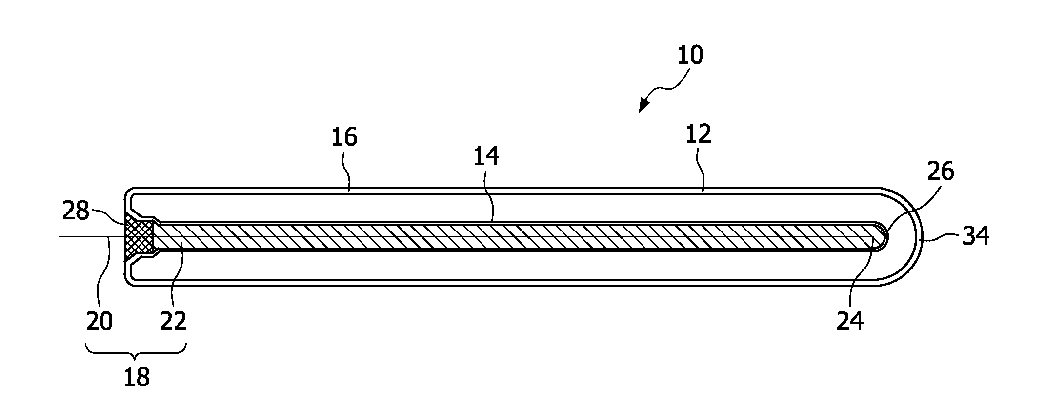
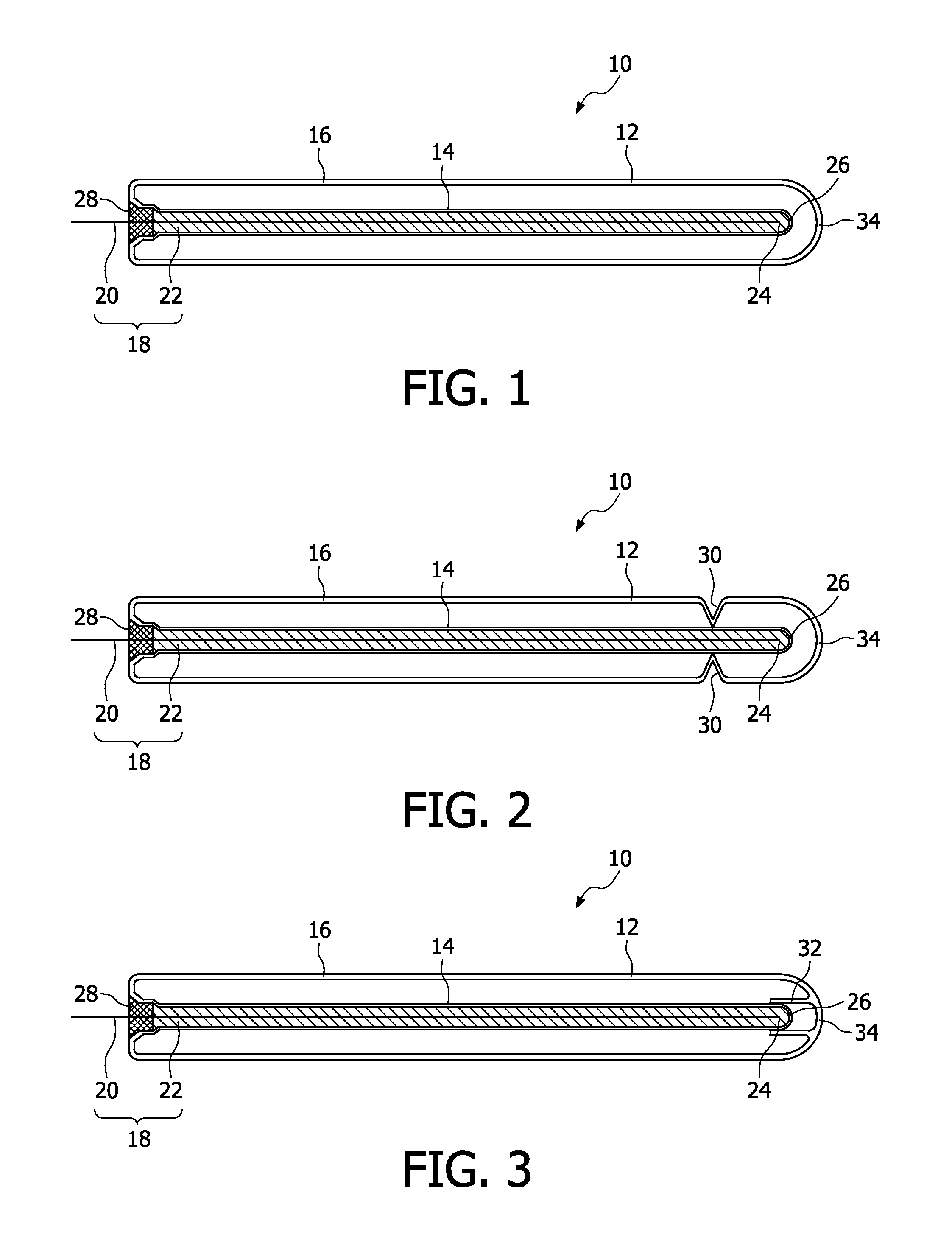
[0023]In the in FIG. 1 illustrated first embodiment of the dielectric barrier discharge lamp 10 according to the invention the dielectric barrier discharge lamp 10 comprises an outer tube 12 and an inner tube 14 arranged coaxial to the outer tube 12. The dielectric barrier discharge lamp 10 comprises an outer electrode 16, which may be a conductive coating or preferably a conductive meshed web. The outer electrode 16 may be arranged on the outside or the inside of the outer tube 12.

[0024]The inner tube 14 comprises an inner electrode 18 consisting of a conductor 20 and a conductive granulated material 22, wherein the inner tube 14 is only partially filled by the conductor 20 and the granulated material 22. For sake of clarity the specific particles of the granulated material and the partial filling of the inner tube 14 are not illustrated in detail. Due to the partial filling of the inner tube 14 by the conductive granulated material 22 an electrical contact between the conductor 20...

second embodiment

[0027]In the dielectric barrier discharge lamp 10 illustrated in FIG. 2 the outer tube 12 comprises grooves 30, by which the inner tube 14 may be at least partially supported. Due to the chosen design of the grooves 30 a vibration or swinging of the inner tube 14 may be prevented leading to an increased mechanical stability of the inner tube 14.

third embodiment

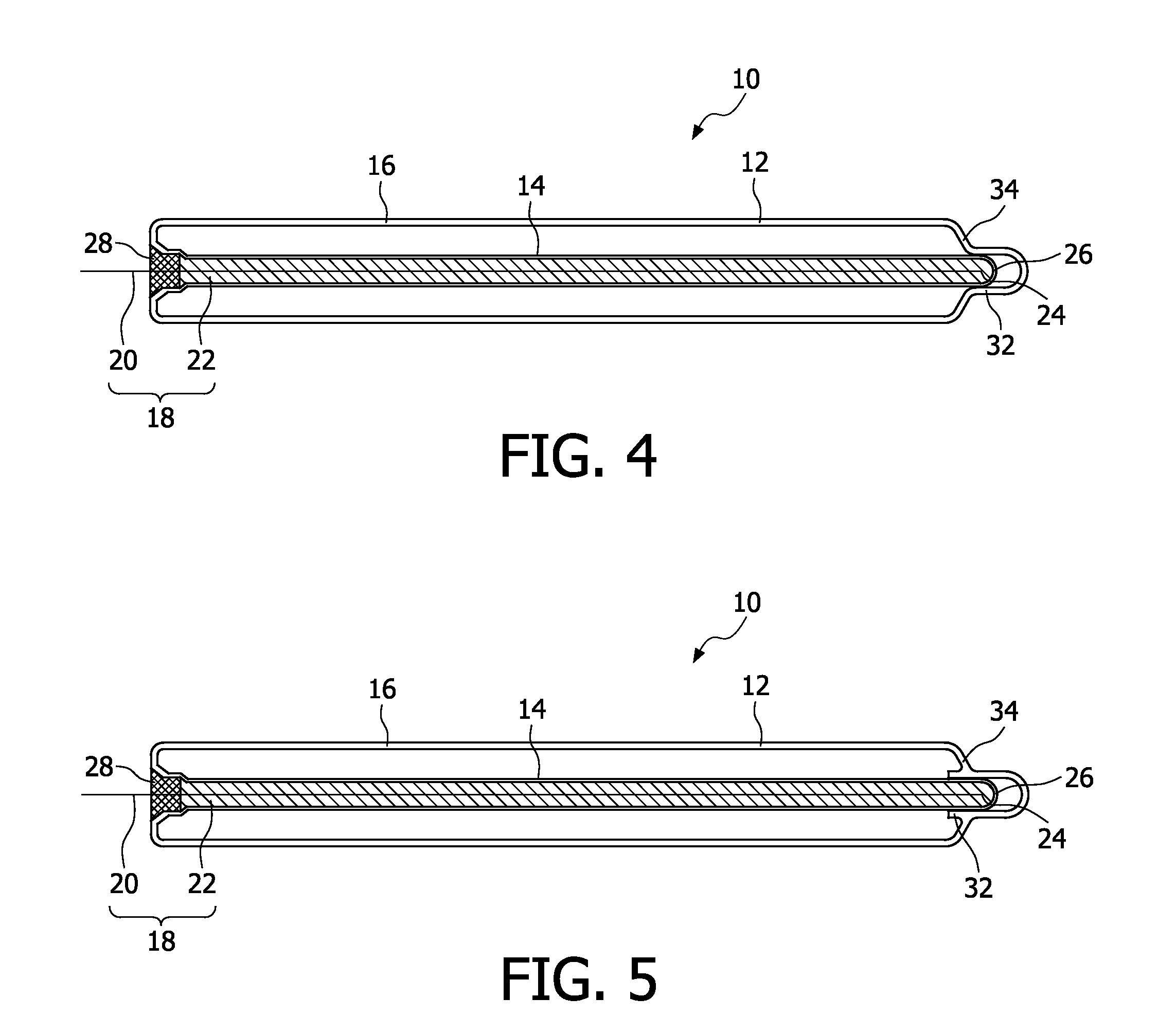
[0028]In the dielectric barrier discharge lamp 10 illustrated in FIG. 3 the increased mechanical stability of the inner tube 14 is provided by a mainly tubular protrusion 32 at a distal front face 34 of the outer tube 12. Between the distal end 26 of the inner electrode 14 and the protrusion 32 is at least a clearance fit or a greater gap provided allowing a thermal expansion of the inner tube 14 in radial direction.


PUM


Abstract

It is provided a dielectric barrier discharge lamp (10) for providing ultraviolet light, comprising an outer tube (12) filled with a discharge gas for providing ultraviolet light, an inner tube (14) arranged at least partially inside the outer tube (12), an outer electrode (16) electrically connected to the outer tube (12) and an inner electrode (18) electrically connected to the inner tube (14), wherein the inner electrode (18) comprises a conductor (20) and a plurality of an conductive granulated material (22) for providing an electrical contact between the conductor (20) and the inner tube (14). Due to the conductive granulated material (22) an electrical contact between the conductor (20) and the inner tube (14) is safeguarded and different thermal expansions of the inner electrode (18) and the inner tube (14) are compensated at the same time without applying mechanical stress to the inner tube (14). This leads to a dielectric barrier discharge lamp (10), which comprises an increased life time without the need for external cooling.

Description

FIELD OF THE INVENTION[0001]The invention relates to the field of dielectric barrier discharge lamps, by which ultraviolet light may be generated for photochemical, photophysical or photobiological reactions like a treatment of liquid or gaseous media.BACKGROUND OF THE INVENTION[0002]Dielectric barrier discharge lamps become hot during operation, so that the dielectric barrier discharge lamp may break due to different thermal expansion of its parts. Thus, it is necessary in many cases to cool the dielectric barrier discharge lamp by means of a coolant like water.[0003]From U.S. Pat. No. 5,666,026 a dielectric barrier discharge lamp is known, which comprises an inner tube arranged inside an outer tube, wherein between the inner tube and the outer tube a discharge gas for providing ultraviolet light is sealed. An outer electrode is provided on the outside of the outer tube and an inner electrode is provided on the inside of the inner electrode, so that the tubes provide a dielectric b...

Claims


Application Information

Patent Timeline
IPC IPC(8): H01J61/04H01J61/30H01J61/36
CPCH01J65/046
Inventor BRAUN, NORBERTGREUEL, GEORG
Owner SIGNIFY HLDG BV
Why Eureka
Try Eureka