Mini-environment apparatus

a technology for a filter unit and an environment, applied in the direction of lighting and heating apparatus, heating types, transportation and packaging, etc., can solve the problems of reducing the operation ability of an apparatus, the workability of the filter unit, etc., and achieves the effect of reducing the time of the apparatus in accordance with its maintenance, reducing the work difficulty, and improving the maintenance efficiency

Active Publication Date: 2017-06-15
TDK CORPARATION
View PDF3 Cites 229 Cited by
  • Summary
  • Abstract
  • Description
  • Claims
  • Application Information

AI Technical Summary

Benefits of technology

[0008]The prevent invention has been achieved under such circumstances and provides a mini-environment apparatus maintaining a clean environment in a wafer transportation room and excelling in maintainability.
[0038]In the mini-environment apparatus, the chemical filter can be replaced while a cleanliness of the circulating passage and the filter transportation room is maintained by shielding the current in the circulating passage due to the shutters. In the mini-environment apparatus, the chemical filter can be easily replaced via the filter removal window, whereby the mini-environment apparatus is excellent in maintainability, and a stop time of the apparatus in accordance with its maintenance can be shortened.

Problems solved by technology

However, the conventional fan filter unit has a structure where the particle removal filter and the chemical filter are integrated, and is uneconomical because the particle removal filter also needs to be replaced at the same time if a replacement frequency of the chemical filter is increased for improvement in a removal efficiency of harmful gas component.
Furthermore, the conventional fan filter unit has a bad workability since the fan filter unit is arranged in the ceiling part of the wafer transportation room, and has a problem of decrease in operation ability of an apparatus if the fan filter unit is frequently replaced.

Method used


Image

  • Mini-environment apparatus
  • Mini-environment apparatus
  • Mini-environment apparatus

Examples


first embodiment

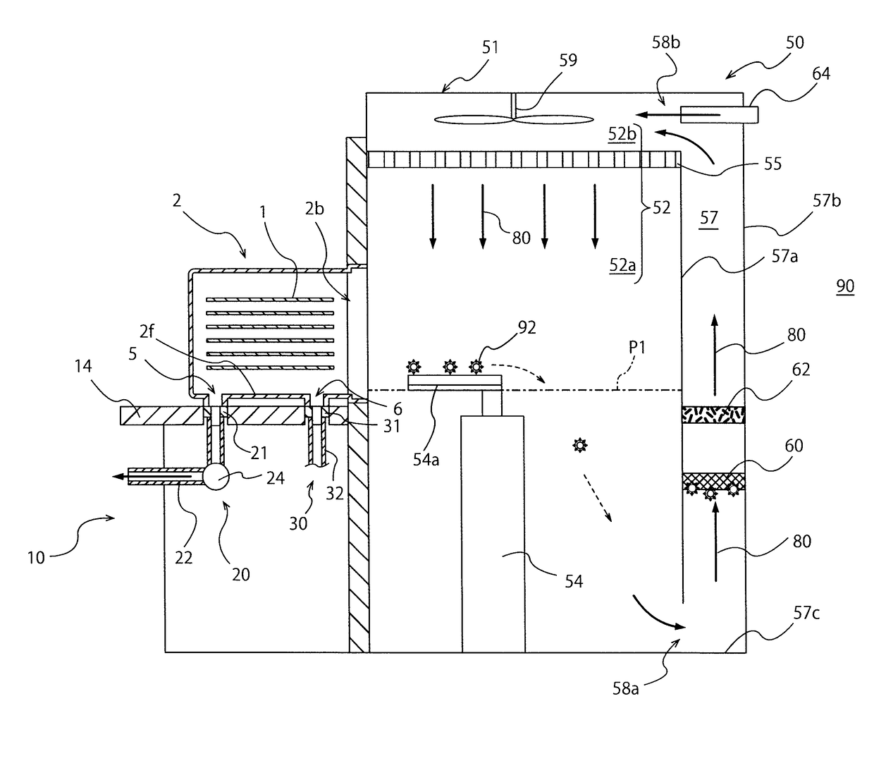
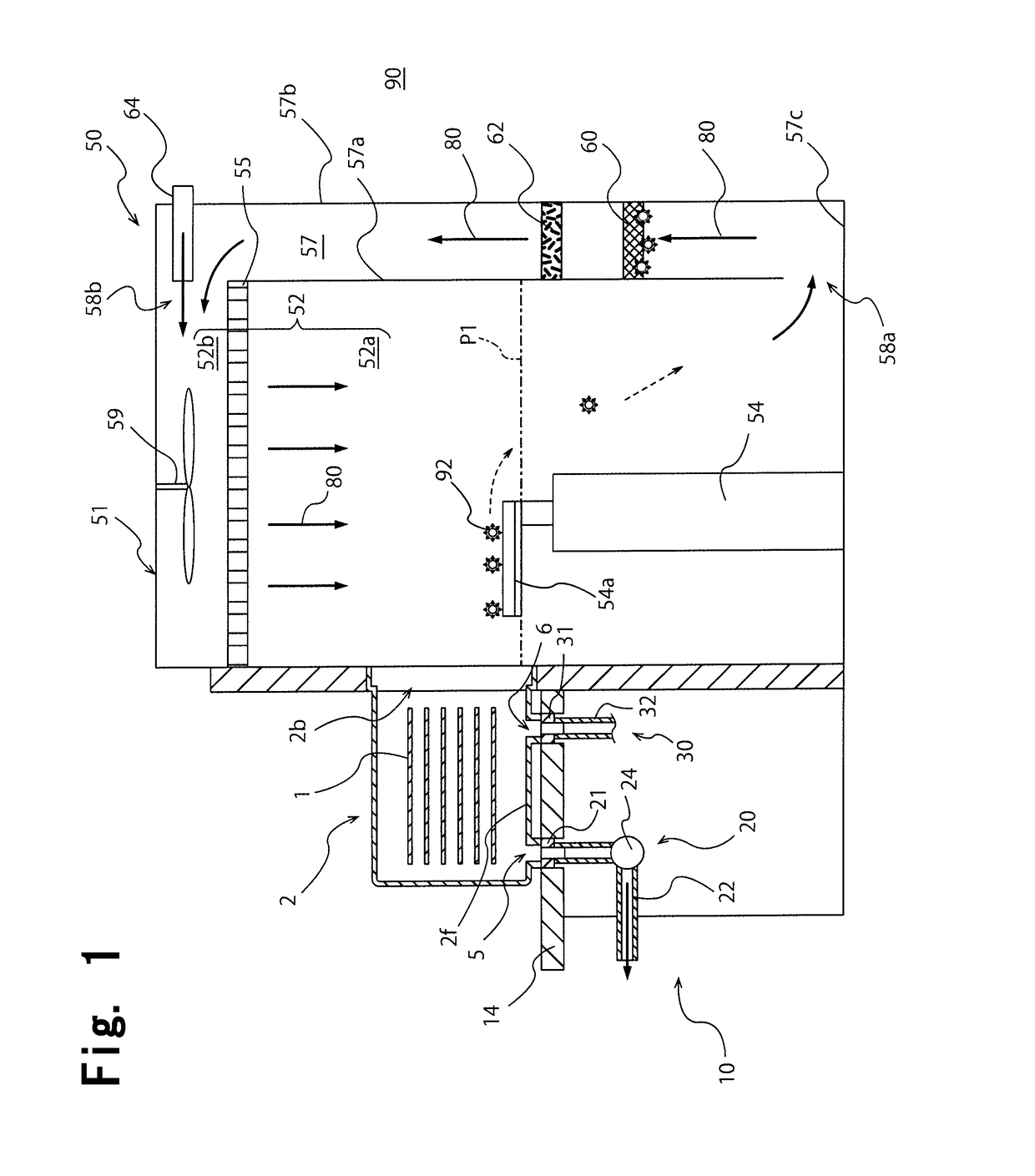
[0043]As shown in FIG. 1, a mini-environment apparatus 51 of the present invention constitutes a part of an Equipment Front End Module (EFEM) 50 of a front end module of a semiconductor processing apparatus. In addition to the mini-environment apparatus 51, the EFEM 50 has a load port device 10.

[0044]The load port device 10 has an installation stand 14 configured to install a Front Opening Unified Pod (FOUP) 2. The FOUP 2 is transported onto the installation stand 14 by a ceiling transportation system, for example. As shown in FIG. 1, the load port device 10 can airtightly connect a main opening 2b of the FOUP 2 installed on the installation stand 14 to a wafer transportation room 52.

[0045]The FOUP 2 installed on the top of the installation stand 14 stores and transports a plurality of wafers 1 as housed objects in a sealed state. A space for housing the wafers 1 is formed inside the FOUP 2. The FOUP 2 has a box shape having a plurality of side surfaces positioned in the horizontal...

second embodiment

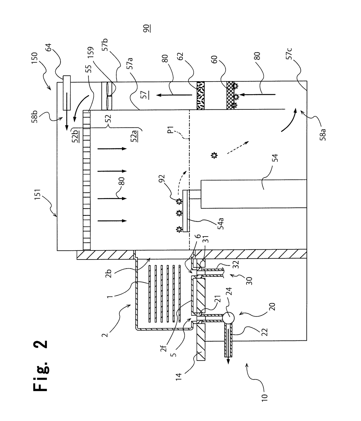
[0075]FIG. 2 is a schematic cross sectional view showing an EFEM 150 containing a mini-environment apparatus 151 of the present invention. The mini-environment apparatus 151 is the same as the mini-environment apparatus 51 shown in FIG. 1 except that a fan 159 as a blow means is not arranged in the ceiling part 52b but in the circulating passage 57. In the mini-environment apparatus 151 shown in FIG. 2, the fan 159 is arranged in the circulating passage 57 and is arranged above the chemical filter 60 and the particle removal filter 62.

[0076]Incidentally, the fan 159 is arranged anywhere in the circulating passage 57, but is preferably arranged at least above the chemical filter 60 so as to prevent a problem that the fan 159 is contaminated by a harmful gas component. As shown in FIG. 2, the fan 159 may be arranged in the circulating passage 57, and the mini-environment apparatus 151 demonstrates the same effect as the mini-environment apparatus 51 shown in FIG. 1.

third embodiment

[0077]FIG. 3 is a schematic cross sectional view showing an EFEM 250 containing a mini-environment apparatus 251 of the present invention. The mini-environment apparatus 251 is the same as the mini-environment apparatus 151 shown in FIG. 2 except that shutters 265 and 266 and a filter removal window 267 are arranged in the circulating passage 57, and except that a particle removal filter 262 is arranged in the ceiling part 52b of the wafer transportation room 52.

[0078]As shown in FIG. 3, the shutters 265 and 266 are arranged in the circulating passage 57 so as to sandwich the chemical filter 60 from up and down directions. The shutters 265 and 266 can be opened and closed, and are closed so as to shield the circulating current 80 in the circulating passage 57. The shutters 265 and 266, however, are opened except when the chemical filter 60 is replaced, and the shutters 265 and 266 do not shield the circulating current 80 in a state where the shutters 265 and 266 are opened. The fil...


PUM


Abstract

A mini-environment apparatus includes a wafer transportation machine transporting a wafer, a wafer transportation room having the machine and passed by the wafer transported to a processing room, a circulating passage where a gas detoured from the transportation room flows, a blowing means forming a circulating current falling in the transportation room and rising in the passage, a current member arranged in a ceiling part of the transportation room and laminarizing the current and introducing this laminarized current into the transportation room, a particle removal filter arranged in either the ceiling part of the transportation room or the passage, and a chemical filter arranged in the passage detachably and separately from the removal filter. The chemical filter is arranged at a position lower than a lowest position where the wafer may pass through in the transportation room.

Description

BACKGROUND OF THE INVENTION[0001]1. Field of the Invention[0002]The present invention relates to a mini-environment apparatus, and more specifically relates to a mini-environment apparatus including a wafer transportation machine and a wafer transportation room where the wafer transportation machine is arranged.[0003]2. Description of the Related Art[0004]In manufacturing steps of semiconductors, wafers are transported between respective processing apparatuses using a container called a FOUP or so. When the wafers are processed, the wafers in the container are transported from a FOUP to a processing room via an Equipment Front End Module (EFEM) equipped with the respective processing apparatuses. The EFEM has a load port device and a mini-environment apparatus. The load port device installs a container for transporting wafers. The mini-environment apparatus connects between a container installed on the load port device and a processing room for processing the wafers.[0005]The mini-e...

Claims


Application Information

Patent Timeline
Patent Type & Authority Applications(United States)
IPC IPC(8): H01L21/67F24F3/16H01L21/677H01L21/673H01L21/687
CPCH01L21/67017H01L21/67389H01L21/67386H01L21/67196F24F2003/1614H01L21/67769H01L21/67775F24F3/161F24F2003/1621H01L21/68707H01L21/677F24F3/167F24F8/108F24F8/15H01L21/67028H01L21/67393
Inventor OKABE, TSUTOMUHORIBE, HIDETOSHI
Owner TDK CORPARATION
Why Eureka
Try Eureka