Mini-environment apparatus
a technology for a filter unit and an environment, applied in the direction of lighting and heating apparatus, heating types, transportation and packaging, etc., can solve the problems of reducing the operation ability of an apparatus, the workability of the filter unit, etc., and achieves the effect of reducing the time of the apparatus in accordance with its maintenance, reducing the work difficulty, and improving the maintenance efficiency
- Summary
- Abstract
- Description
- Claims
- Application Information
AI Technical Summary
Benefits of technology
Problems solved by technology
Method used
Image
Examples
first embodiment
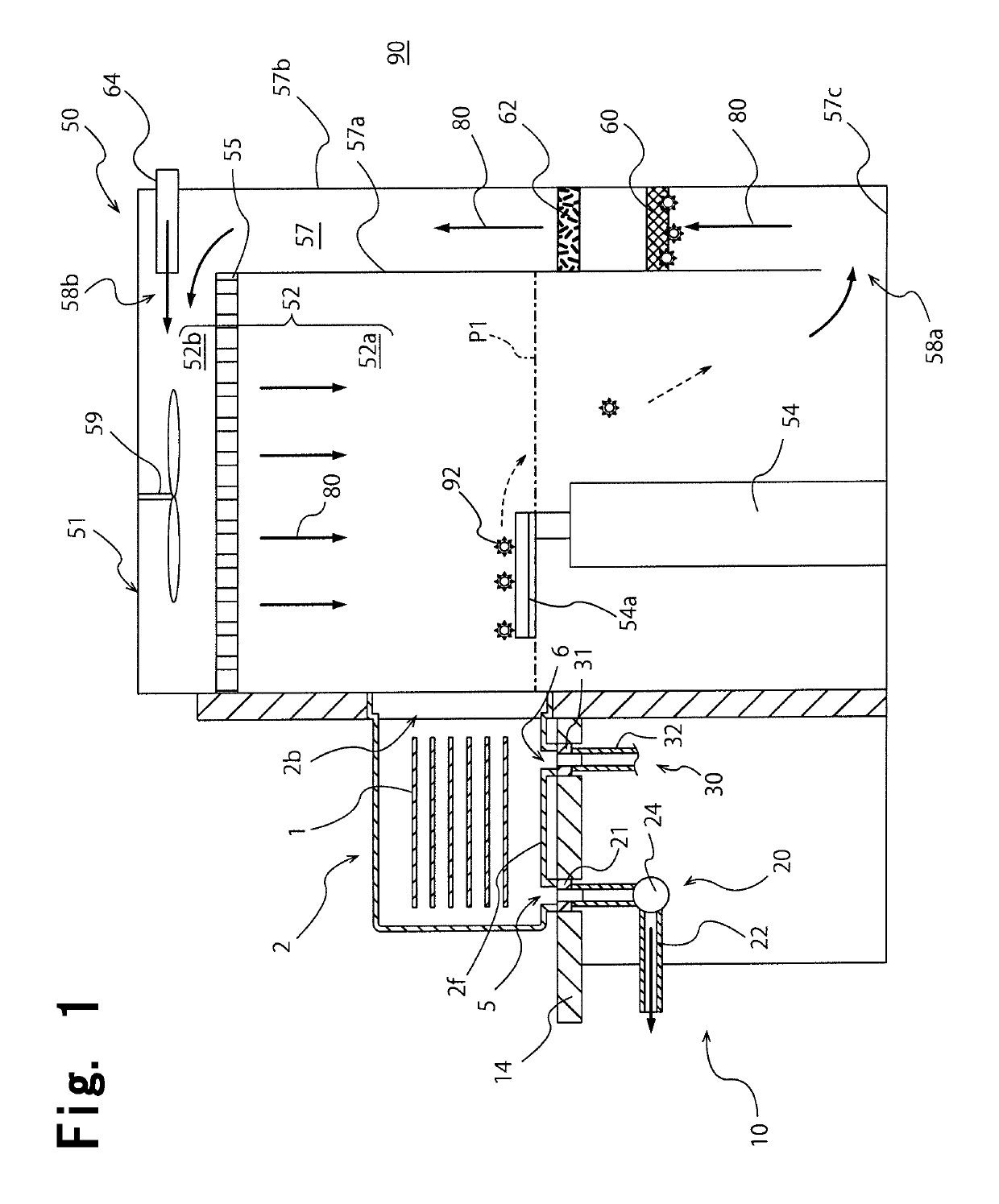
[0043]As shown in FIG. 1, a mini-environment apparatus 51 of the present invention constitutes a part of an Equipment Front End Module (EFEM) 50 of a front end module of a semiconductor processing apparatus. In addition to the mini-environment apparatus 51, the EFEM 50 has a load port device 10.
[0044]The load port device 10 has an installation stand 14 configured to install a Front Opening Unified Pod (FOUP) 2. The FOUP 2 is transported onto the installation stand 14 by a ceiling transportation system, for example. As shown in FIG. 1, the load port device 10 can airtightly connect a main opening 2b of the FOUP 2 installed on the installation stand 14 to a wafer transportation room 52.
[0045]The FOUP 2 installed on the top of the installation stand 14 stores and transports a plurality of wafers 1 as housed objects in a sealed state. A space for housing the wafers 1 is formed inside the FOUP 2. The FOUP 2 has a box shape having a plurality of side surfaces positioned in the horizontal...
second embodiment
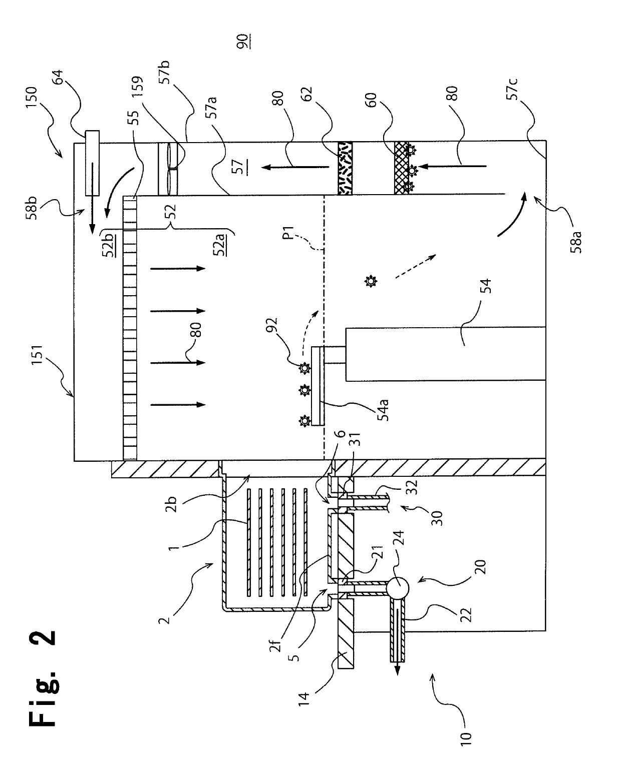
[0075]FIG. 2 is a schematic cross sectional view showing an EFEM 150 containing a mini-environment apparatus 151 of the present invention. The mini-environment apparatus 151 is the same as the mini-environment apparatus 51 shown in FIG. 1 except that a fan 159 as a blow means is not arranged in the ceiling part 52b but in the circulating passage 57. In the mini-environment apparatus 151 shown in FIG. 2, the fan 159 is arranged in the circulating passage 57 and is arranged above the chemical filter 60 and the particle removal filter 62.
[0076]Incidentally, the fan 159 is arranged anywhere in the circulating passage 57, but is preferably arranged at least above the chemical filter 60 so as to prevent a problem that the fan 159 is contaminated by a harmful gas component. As shown in FIG. 2, the fan 159 may be arranged in the circulating passage 57, and the mini-environment apparatus 151 demonstrates the same effect as the mini-environment apparatus 51 shown in FIG. 1.
third embodiment
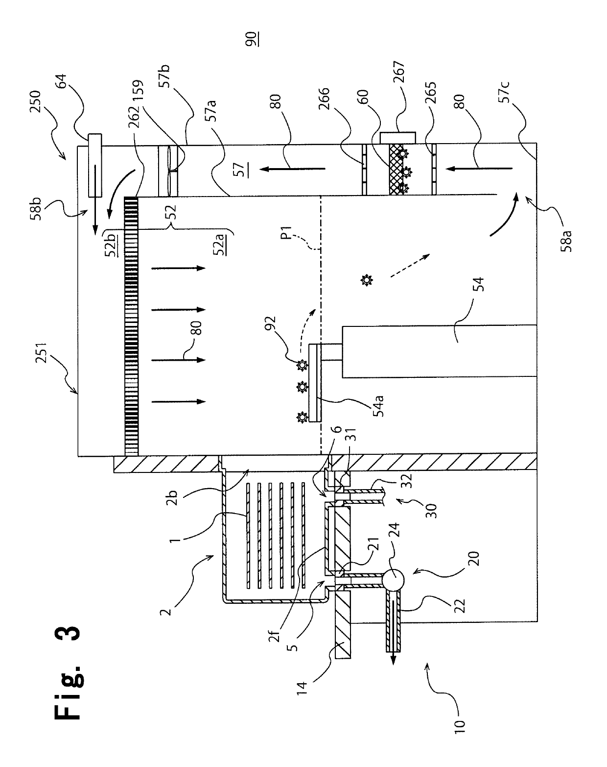
[0077]FIG. 3 is a schematic cross sectional view showing an EFEM 250 containing a mini-environment apparatus 251 of the present invention. The mini-environment apparatus 251 is the same as the mini-environment apparatus 151 shown in FIG. 2 except that shutters 265 and 266 and a filter removal window 267 are arranged in the circulating passage 57, and except that a particle removal filter 262 is arranged in the ceiling part 52b of the wafer transportation room 52.
[0078]As shown in FIG. 3, the shutters 265 and 266 are arranged in the circulating passage 57 so as to sandwich the chemical filter 60 from up and down directions. The shutters 265 and 266 can be opened and closed, and are closed so as to shield the circulating current 80 in the circulating passage 57. The shutters 265 and 266, however, are opened except when the chemical filter 60 is replaced, and the shutters 265 and 266 do not shield the circulating current 80 in a state where the shutters 265 and 266 are opened. The fil...
PUM
 Abstract
Description
Claims
Application Information
 - R&D
- Intellectual Property
- Life Sciences
- Materials
- Tech Scout
- Unparalleled Data Quality
- Higher Quality Content
- 60% Fewer Hallucinations
Browse by: Latest US Patents, China's latest patents, Technical Efficacy Thesaurus, Application Domain, Technology Topic, Popular Technical Reports.
© 2025 PatSnap. All rights reserved.Legal|Privacy policy|Modern Slavery Act Transparency Statement|Sitemap|About US| Contact US: help@patsnap.com


