Rotary movable side vane lift force generating device

A generating device and lift technology, applied in the direction of passing through cylindrical rotating parts, etc., can solve the problems of poor structural strength, low-speed flight performance of fixed-wing aircraft, and inability to lift vertically

Inactive Publication Date: 2015-07-29
FOSHAN SHENFENG AVIATION SCI & TECH
View PDF7 Cites 1 Cited by
  • Summary
  • Abstract
  • Description
  • Claims
  • Application Information

AI Technical Summary

Problems solved by technology

The relative thickness of the wing and the rotor are relatively thin, and the structural strength is poor
The low-speed flight

Method used


Image

  • Rotary movable side vane lift force generating device
  • Rotary movable side vane lift force generating device
  • Rotary movable side vane lift force generating device

Examples


Embodiment Construction

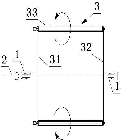
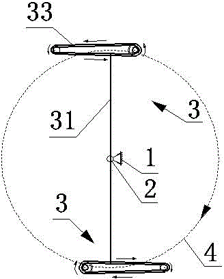
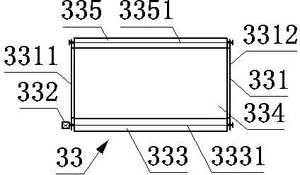
[0010] Now in conjunction with accompanying drawing, the present invention is described in detail: a kind of rotating dynamic wing lift generation device, comprises frame 1, main shaft 2 and two, three or four structurally identical rotors 3 evenly distributed around main shaft 2; The main shaft 2 is arranged horizontally, and the left end and the right end of the main shaft 2 are installed on the frame 1 through bearings respectively. Each rotating wing 3 comprises a left rotating arm 31, a right rotating arm 32 and a moving wing 33; The moving surface wing 33 comprises wing body 331, motor 332, driving roller 333, airfoil 334 and driven roller 335; airfoil 334 is wrapped in wing body 331, driving roller 333 and driven roller 335 outside; The two ends are respectively installed on the left end plate 3311 of the wing body and the right end plate 3312 of the wing body through bearings; the motor 332 is connected with the driving roller shaft 3331; On the right end plate 3312 o...


PUM


Abstract

The invention provides a rotary movable side vane lift force generating device and belongs to the technical field of aviation. The rotary movable side vane lift force generating device comprises a rack, a main shaft, and two, three or four same-structure rotary vanes uniformly distributed at the periphery of the main shaft; the main shaft is arranged horizontally; the left end and the right end of the main shaft are respectively arranged on the rack by virtue of bearings; each rotary vane comprises a left rotary arm, a right rotary arm and a movable side vane; the left rotary arms are parallel to the right rotary arms, and the left rotary arms and the right rotary arms are vertically connected with the main shaft; each movable side vane is parallel to the main shaft; each movable side vane comprises a vane body, a motor, a drive roll, an airfoil and a driven roll; each motor is connected with a drive roll shaft; driven by the motors, the drive rolls are capable of rotating to drive the airfoils and the driven rolls to rotate. During a process of passing above the horizontal surface of the main shaft, the airfoil rotation direction of each movable side vane is a counterclockwise direction; during a process of passing below the horizontal surface of the main shaft, the airfoil rotation direction of each movable side vane is a clockwise direction. The device is capable of generating an upward lift force. Serving as a lifting device, the device can be applied to a vertical-lift aerocraft.

Description

technical field [0001] A rotating dynamic wing lift generating device belongs to the field of aviation technology, and in particular relates to a moving wing lift generating device. Background technique [0002] Traditional aircraft rely on wings or rotors to generate lift. The structure of aircraft wings and helicopter rotors is similar. Their cross-sections are all airfoils. When determined, the magnitude of the lift they produce is related to the angle of attack, the size of the airfoil and the velocity of the incoming flow, and the adjustment of the magnitude of the lift is achieved by changing the angle of attack, speed or the size of the airfoil. The relative thickness of the wing and the rotor is relatively thin, and the structural strength is relatively poor. The low-speed flight performance of fixed-wing aircraft is not high, and the wing area required at low speed is relatively large, and it cannot vertically lift. Helicopter rotor speed is very high to produce g...

Claims


Application Information

Patent Timeline
IPC IPC(8): B64C23/02
Inventor 王志成
Owner FOSHAN SHENFENG AVIATION SCI & TECH
Why Eureka
Try Eureka