Supercharge Your Innovation With Domain-Expert AI Agents!

Method for Manufacturing a Liquid-Tight Slide Fastener

a technology of liquid tightener and manufacturing method, which is applied in the direction of slide fasteners, metal working equipment, metal-working equipment, etc., can solve the problems of deteriorating the efficiency of sewing operation of the slide fastener, water invading the joint portion, and inability to ensure the effect of water repellent treatment, etc., to achieve the effect of improving the water repellent effect or oil repellent effect of the entire liquid tightener, improving the predetermined water repellency, and reducing the number of a liquid-tightening slide fastener and liquid-tightening and sealing slide fastener liquid-tightening and sealing and liquid-tightening and manufacturing method liquid-tightening and manufacturing method, a technology of liquid-tightening and sealing technology, applied in the field of liquid-tightening effect of the entire liquid-tightness of the entire effect, improving water-tightness of the entire liquid-tightness of the entire liquid-tightness of the liquid-tightness of the liquid-tightness of the liquid-tightness of the liquid-tightness of the liquid-tightness of the liquid-tightness of the liquid-tightness of the liquid-

Inactive Publication Date: 2012-01-19
YKK CORP
View PDF41 Cites 1 Cited by
  • Summary
  • Abstract
  • Description
  • Claims
  • Application Information

AI Technical Summary

Benefits of technology

[0014]The present invention has been made to solve these problems possessed by the prior art, and an object of the invention is to improve the water repellent and oil repellent performance of the slide fastener without providing with any special water stop flap.

Problems solved by technology

Thus, although the effect of water repellency can be expected to some extent, there is still generated such a fault that water invades through the joint portion.
Further, the water repellent treatment is never performed securely on the joint portion between the stringer tapes 814 and 816.
However, if the water stop flat is provided on the slide fastener, efficiency of sewing operation for the slide fastener is deteriorated and it becomes very difficult to open / close the slide fastener.

Method used


Image

  • Method for Manufacturing a Liquid-Tight Slide Fastener
  • Method for Manufacturing a Liquid-Tight Slide Fastener
  • Method for Manufacturing a Liquid-Tight Slide Fastener

Examples


Embodiment Construction

[0042]Hereinafter, typical embodiments of a liquid-tight slide fastener of the present invention will be described in detail with reference to the accompanying drawings.

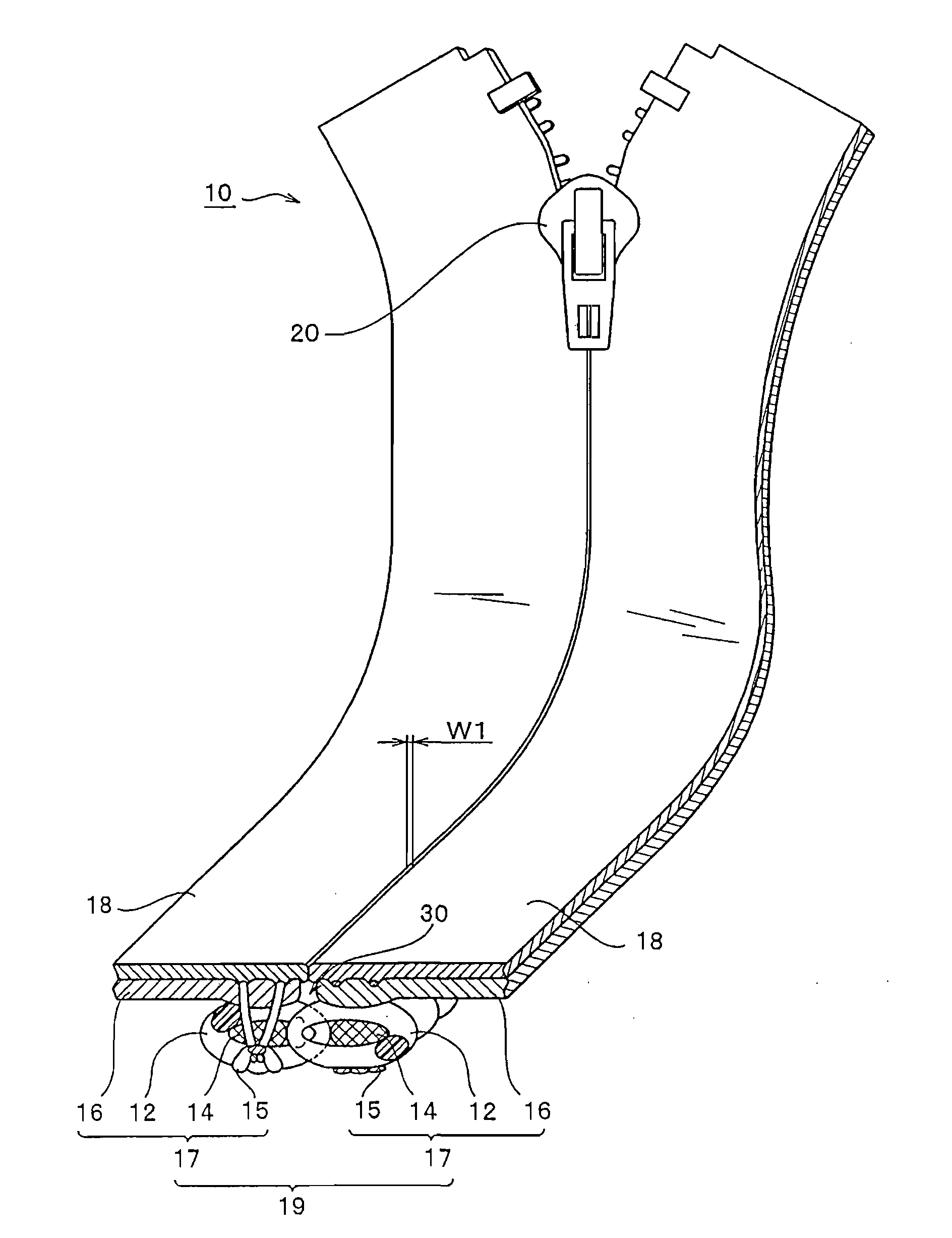
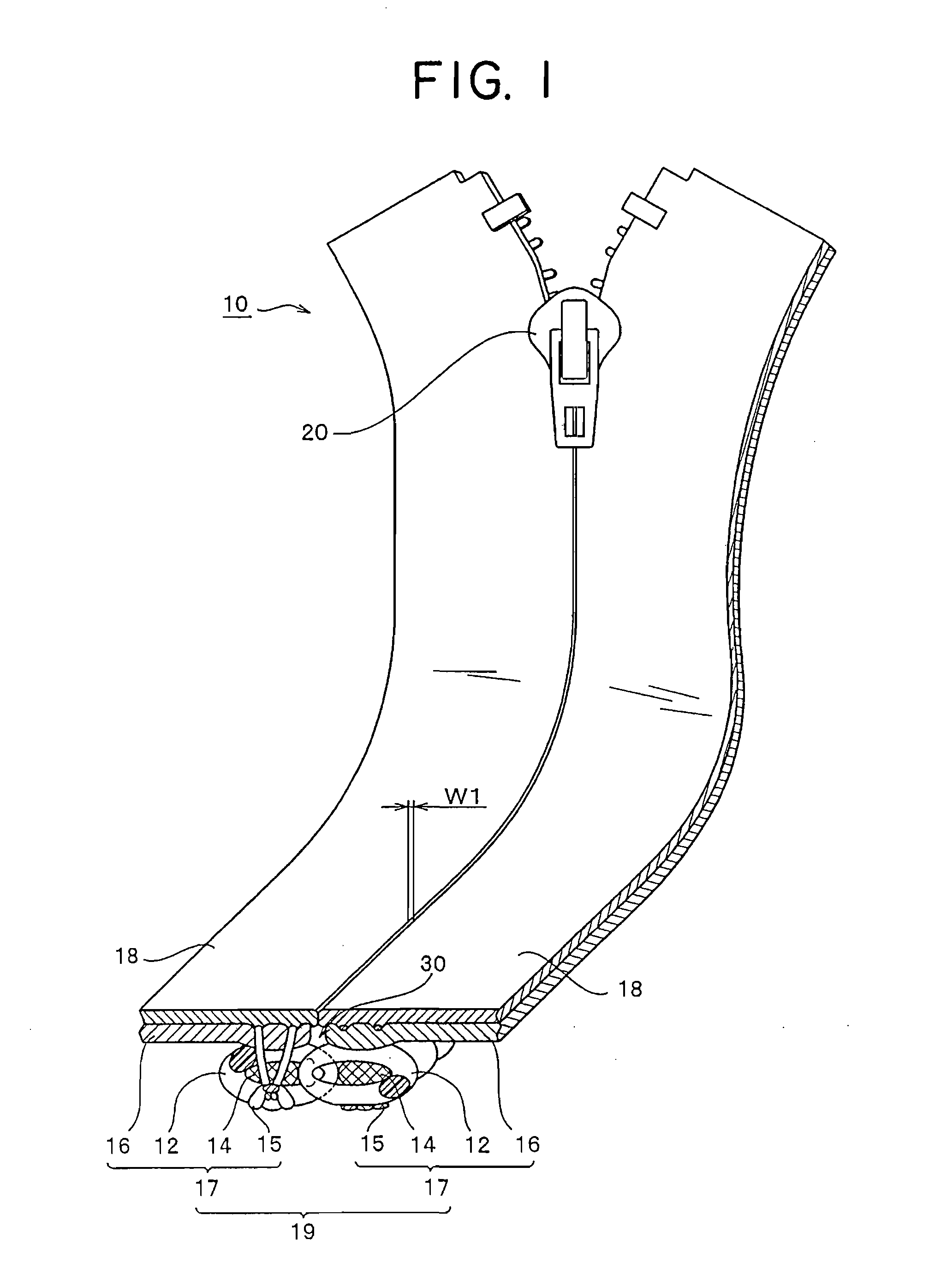
[0043]FIG. 1 is an external perspective view of a liquid-tight slide fastener according to a first embodiment of the present invention. FIG. 1 shows a section obtained by cutting a part of the liquid-tight slide fastener in order to explain the interior of coupling element rows.

[0044]As shown in FIG. 1, a liquid-tight slide fastener 10 of the present invention includes a pair of right and left coil-like coupling element rows 12, a core thread 14 whose surface is coated with a water repellent agent, a pair of fastener stringers 17 obtained by sewing the coupling element rows 12 and the core thread 14 along opposing side edges of fastener tapes 16 with a sewing yarn 15, a slider 20 caused to slide when the pair of coupling element rows 12 are coupled with or decoupled from each other, and a liquid-tight layer 18 for co...


PUM

PropertyMeasurementUnit
angle of contactaaaaaaaaaa
angleaaaaaaaaaa
lengthaaaaaaaaaa

Abstract

A liquid-tight slide fastener, wherein a pair of right and left coil-like coupling element rows, through which a core thread is respectively passed, is attached by sewing along opposing side edges of a pair of right and left fastener tapes, the fastener tapes having a liquid-tight layer on one surface thereof, and the core thread is coated with a water repellent agent or oil repellent agent. Consequently, even if water or oil invades into a space portion in the coupling element rows through a joint portion in the liquid-tight slide fastener, the core thread repels the water or oil, thereby blocking a further invasion of water or oil, and exerting excellent water repellency or oil repellency without provision of a water stop flap.

Description

BACKGROUND OF THE INVENTION[0001]1. Field of the Invention[0002]The present invention relates to a liquid-tight slide fastener for use at an opening of clothes, cases, bags and the like requiring water repellency or oil repellency and a method for manufacturing the liquid-tight slide fastener.[0003]2. Description of the Related Art[0004]Conventionally, there has been known a slide fastener having waterproof property due to lamination of a polyurethane film on the surface of a fastener tape on an opposite side to a coupling element mounting surface of a slide fastener on which coil-like coupling element rows are sewed. FIG. 13 shows a perspective view of the slide fastener having waterproof property. In the meantime, FIG. 13 shows a part of the slide fastener.[0005]As shown in FIG. 13, a slide fastener 910 includes a pair of right and left coil-like coupling element rows 912, a pair of fastener tapes 916, and a slider 920. A core thread 914 is passed through the pair of right and lef...

Claims


Application Information

Patent Timeline
Patent Type & Authority Applications(United States)
IPC IPC(8): B23P11/00
CPCA44B19/12A44B19/32Y10T29/49782Y10T24/2514Y10T24/2523Y10T29/49826A44B19/26A44B19/30
Inventor KUSAYAMA, MASAHIRO
Owner YKK CORP
Features
  • R&D
  • Intellectual Property
  • Life Sciences
  • Materials
  • Tech Scout
  • Unparalleled Data Quality
  • Higher Quality Content
  • 60% Fewer Hallucinations
Learn More