Liquid ejector comprising detachable discharge tank

a liquid ejector and discharge tank technology, applied in printing, other printing apparatus, etc., can solve the problems of shortened life of inkjet recording apparatus, inability to perform suction purge, and inability to use inkjet recording apparatus, so as to keep the structure of the liquid ejector simple

Active Publication Date: 2012-12-04
BROTHER KOGYO KK
View PDF29 Cites 0 Cited by
  • Summary
  • Abstract
  • Description
  • Claims
  • Application Information

AI Technical Summary

Benefits of technology

[0007]An object of the present invention is to provide a liquid ejector with long life.
[0009]In the first aspect of the present invention, the pump is driven while the first valve does not cut off the first tank from the outside air whereas the second valve cuts off the first tank from the second tank. With this, via the cap, the liquid in the liquid ejection head is sucked through the nozzle and conveyed to the first tank. In the meanwhile, the pump is driven while the first valve cuts off the first tank from the outside air whereas the second valve does not cut off the first tank from the second tank. With this, the liquid stored in the first tank is conveyed to the second tank. The amount of the liquid in the first tank is reduced as a result, and hence a space for storing liquid is created in the first tank. It therefore becomes possible to continue the operation of sucking a liquid from the liquid ejection head and conveying the liquid to the first tank through the discharge path. This elongates the life of the liquid ejector.
[0010]Furthermore, as discussed above, the pump can function as not only a power source for sucking the liquid in the liquid ejection head through the nozzle and conveying the liquid to the first tank but also for conveying the liquid from the first tank to the second tank, because of the switching by the first valve and the second valve. Therefore it is unnecessary to provide different power sources and hence the structure of the liquid ejector is kept simple.

Problems solved by technology

This inkjet recording apparatus recited in Japanese Unexamined Patent Publication No. 2007-8156, however, is disadvantageous in that suction purge cannot be performed any more when the waste-liquid foam is saturated with the absorbed ink because of repeated suction purge.
Consequently the inkjet recording apparatus becomes unavailable even if components other than the waste-liquid foam, such as an inkjet head, are still usable.
This results in shortened life of the inkjet recording apparatus.

Method used


Image

  • Liquid ejector comprising detachable discharge tank
  • Liquid ejector comprising detachable discharge tank
  • Liquid ejector comprising detachable discharge tank

Examples


Embodiment Construction

[0025]The following describes a preferred embodiment of the present invention.

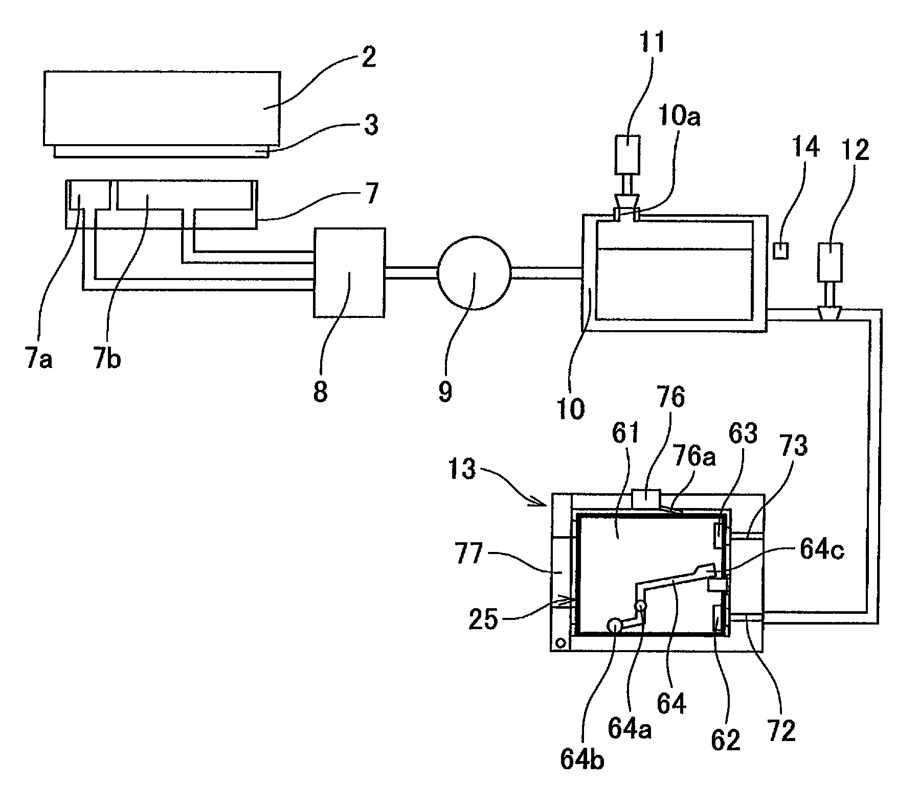
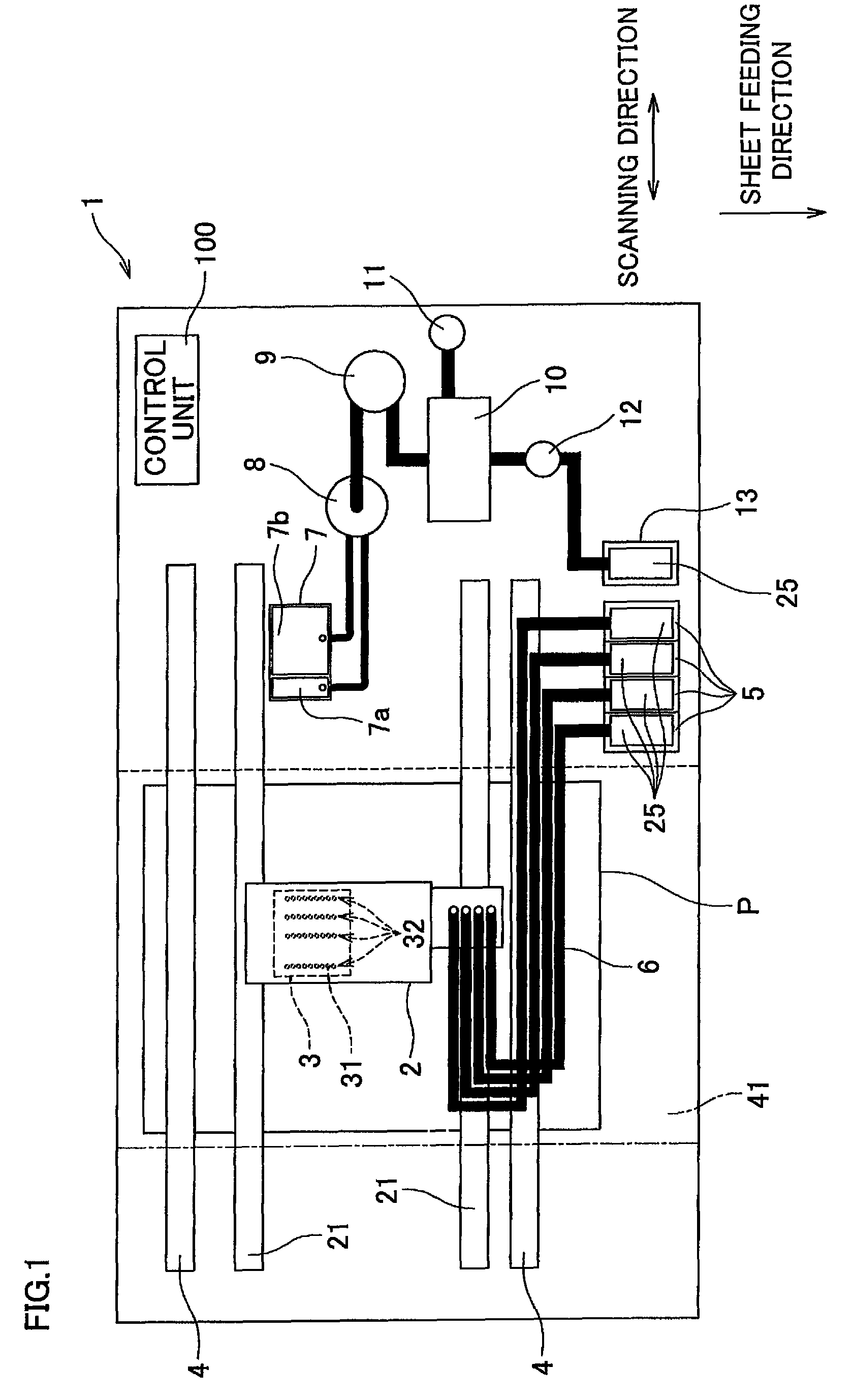
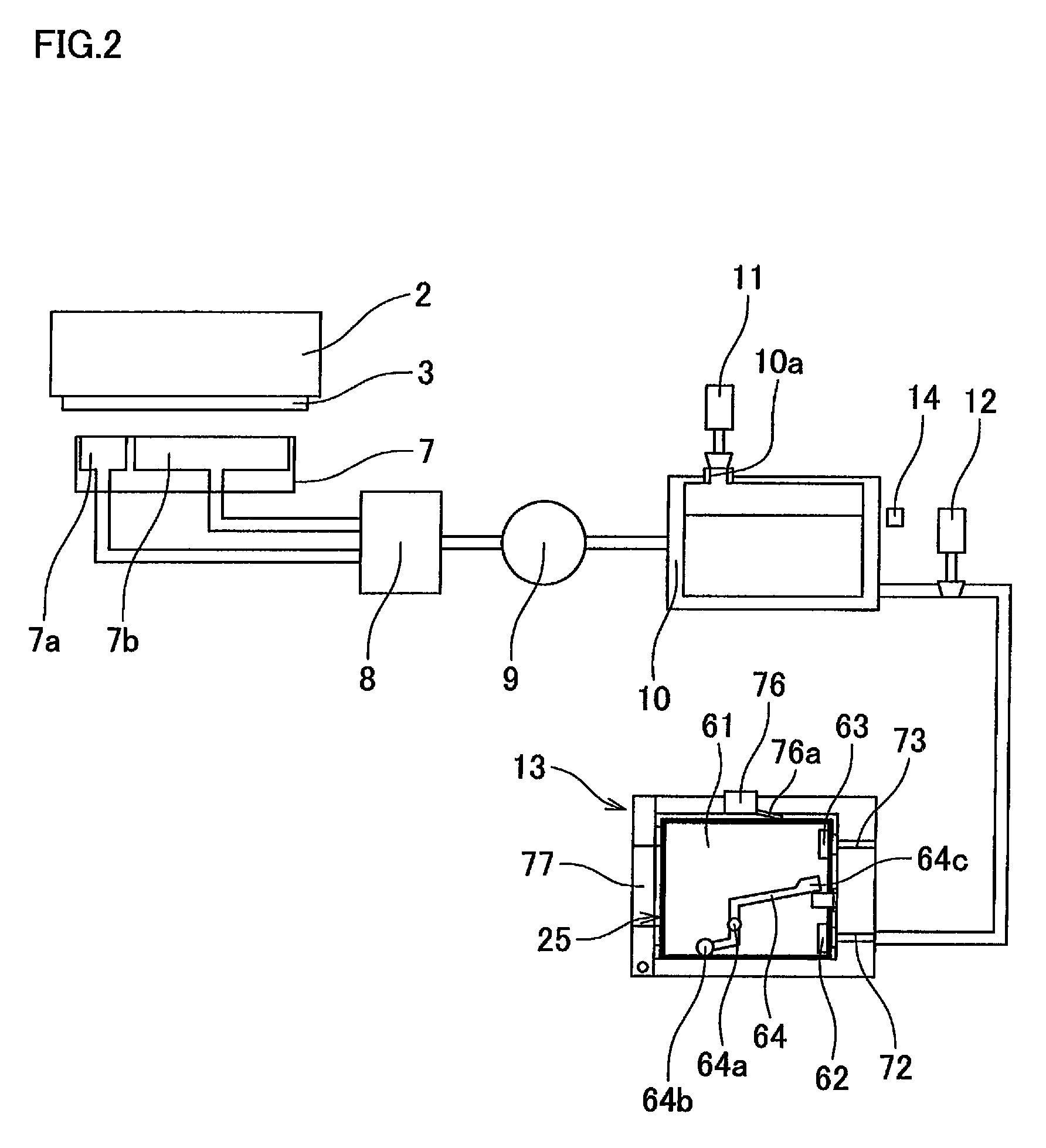
[0026]FIG. 1 is a schematic diagram of a printer of the present invention. FIG. 2 illustrates an ink discharge path which has the upstream end connected to a later-detailed suction cap 7 of FIG. 1 and the downstream end connected to a second cartridge attaching unit 13. As shown in FIGS. 1 and 2, the printer 1 includes components such as a carriage 2, an inkjet head 3, a sheet feeding roller 4, a first cartridge attaching unit 5, tubes 6, a suction cap 7, a switching unit 8, a pump 9, a storage tank 10, and the second cartridge attaching unit 13. The operation of the printer 1 is controlled by the control unit 100.

[0027]The carriage 2 is driven by an unillustrated driver so as to reciprocate along the scanning directions in parallel to the crosswise direction in FIG. 1, i.e. reciprocate in the scanning directions along two guides 21 extending perpendicular to a predetermined direction of the present invent...


PUM


Abstract

A liquid ejector includes a liquid ejection head, a discharge path, a cap, a pump, a first tank, a second tank, a first valve, and a second valve. The liquid ejection head ejects liquid through a nozzle. The cap covers the nozzle. The pump sucks the liquid from the liquid ejection head through the cap and the nozzle and conveys the liquid to a downstream end of the discharge path. The first tank communicates with the outside air, and temporarily stores the liquid in the discharge path. The second tank is detachably attached to the liquid ejector and is connected to the downstream end of the discharge path. The first valve switches the state of the first tank between open to and cut off from the outside air. The second valve switches the state of the first tank between connection to and cut off from the second tank.

Description

CROSS REFERENCE TO RELATED APPLICATION[0001]The present application claims priority from Japanese Patent Application No. 2007-308203, which was filed on Nov. 29, 2007, the disclosure of which is herein incorporated by reference in its entirety.BACKGROUND OF THE INVENTION[0002]1. Field of the Invention[0003]The present invention relates to a liquid ejector which ejects a liquid from a nozzle.[0004]2. Description of Related Art[0005]Japanese Unexamined Patent Publication No. 2007-8156 recites an inkjet recording apparatus in which a suction pump connected to a suction cap is driven while a nozzle of the inkjet head is sealed with the suction cap, with the result that suction purge by which ink is sucked through the nozzle is performed and the sucked ink is absorbed by an waste-liquid foam.SUMMARY OF THE INVENTION[0006]This inkjet recording apparatus recited in Japanese Unexamined Patent Publication No. 2007-8156, however, is disadvantageous in that suction purge cannot be performed an...

Claims


Application Information

Patent Timeline
Patent Type & Authority Patents(United States)
IPC IPC(8): B41J2/165
CPCB41J2/16523B41J2/16532B41J2/17509B41J2/17553B41J2/17566B41J2/17596B41J29/38
Inventor UMEDA, TAKAICHIRO
Owner BROTHER KOGYO KK
Why Eureka
Try Eureka